FPGA Registers | Maps and Registers |
|
|
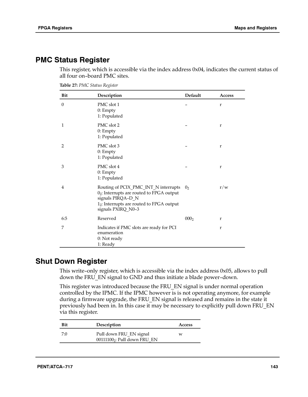
PMC Status Register
This register, which is accessible via the index address 0x04, indicates the current status of all four on−board PMC sites.aaa
Table 27: PMC Status Register
Bit | Description | Default | Access |
0 | PMC slot 1 | − | r |
| 0: Empty |
|
|
| 1: Populated |
|
|
1 | PMC slot 2 | − | r |
| 0: Empty |
|
|
| 1: Populated |
|
|
2 | PMC slot 3 | − | r |
| 0: Empty |
|
|
| 1: Populated |
|
|
3 | PMC slot 4 | − | r |
| 0: Empty |
|
|
| 1: Populated |
|
|
4 | Routing of PCIX_PMC_INT_N interrupts | 02 | r/w |
| 02: Interrupts are routed to FPGA output |
|
|
| signals PIRQA−D_N |
|
|
| 12: Interrupts are routed to FPGA output |
|
|
| signals PXIRQ_N0−3 |
|
|
6:5 | Reserved | 0002 | r |
7 | Indicates if PMC slots are ready for PCI | aa | r |
| enumeration |
|
|
0: Not ready
1: Ready
Shut Down Register
This write−only register, which is accessible via the index address 0x05, allows to pull down the FRU_EN signal to GND and thus initiate a blade power−down.a
This register was introduced because the FRU_EN signal is under normal operation controlled by the IPMC. If the IPMC however is is not operating anymore, for example during a firmware upgrade, the FRU_EN signal is released and remains in the state it previously had been in. In this case it may be necessary to explicitly pull down FRU_EN via this register.a
Bit | Description | Access |
7:0 | Pull down FRU_EN signal | w |
| 001111002: Pull down FRU_EN |
|
PENT/ATCA−717 | 143 |