On−Board Connectors | Controls, Indicators, and Connectors |
|
|
Diff. Pair
Diff. Pair
Diff. Pair
Diff. Pair
Diff. Pair
Diff. Pair
Diff. Pair
Diff. Pair
Diff. Pair
Diff. Pair
Diff. Pair
Diff. Pair
{1 ETHA_DA+
3 ETHA_DA−
5 GND
{7 ETHA_DB+
9 ETHA_DB−
11 GND
{13 ETHB_DA+
15 ETHB_DA−
17 GND
{19 ETHB_DB+
21 ETHB_DB−
23 NETREF
25 PMC_IO_25
27 n.c.
29 PMC_IO_29
31 CLK8_B or PMC_IO_31
{33 PMC_IO_33
35 PMC_IO_35
{37 PMC_IO_37
39 PMC_IO_39
{41 PMC_IO_41
43 PMC_IO_43
{45 PMC_IO_45
47 PMC_IO_47
{49 PMC_IO_49
51 PMC_IO_51
{53 PMC_IO_53
55 PMC_IO_55
{57 PMC_IO_57
59 PMC_IO_59
{61 PMC_IO_61
63 PMC_IO_63
ETHA_DC+
ETHA_DC−
GND ETHA_DD+ ETHA_DD−
GND ETHB_DC+ ETHB_DC−
GND ETHB_DD+ ETHB_DD− n.c. PMC_IO_26 PMC_IO_28
CLK8_A or PMC_IO_30 n.c.
PMC_IO_34
PMC_IO_36
PMC_IO_38
PMC_IO_40
PMC_IO_42
PMC_IO_44
PMC_IO_46
PMC_IO_48 n.c. PMC_IO_52 PMC_IO_54 n.c. PMC_IO_58 PMC_IO_60 PMC_IO_62 PMC_IO_64
24 } Diff. Pair
6
108 } Diff. Pair
12
1416 } Diff. Pair
18
2022 } Diff. Pair
24
2628 } Diff. Pair
30
32
3436 } Diff. Pair
3840 } Diff. Pair
4244 } Diff. Pair
4648 } Diff. Pair
50
5254 } Diff. Pair
56
5860 } Diff. Pair
6264 } Diff. Pair
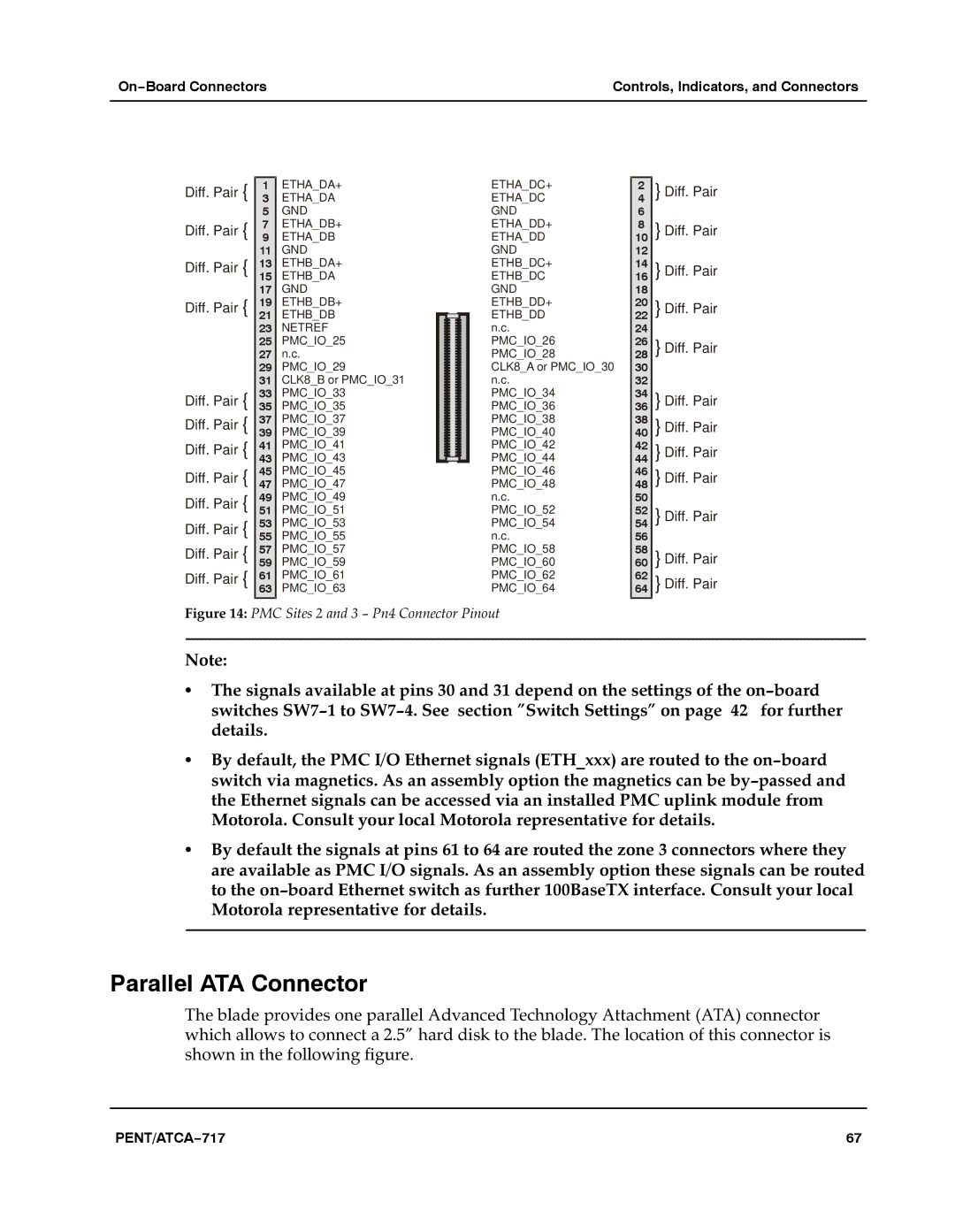
Figure 14: PMC Sites 2 and 3 − Pn4 Connector Pinout
Note:a
SThe signals available at pins 30 and 31 depend on the settings of the on−board switches SW7−1 to SW7−4. Seeasection "Switch Settings" on pagea42a for further details.a
SBy default, the PMC I/O Ethernet signals (ETH_xxx) are routed to the on−board switch via magnetics. As an assembly option the magnetics can be by−passed and the Ethernet signals can be accessed via an installed PMC uplink module from Motorola. Consult your local Motorola representative for details.a
SBy default the signals at pins 61 to 64 are routed the zone 3 connectors where they are available as PMC I/O signals. As an assembly option these signals can be routed to the on−board Ethernet switch as further 100BaseTX interface. Consult your local Motorola representative for details.a
Parallel ATA Connector
The blade provides one parallel Advanced Technology Attachment (ATA) connector which allows to connect a 2.5" hard disk to the blade. The location of this connector is shown in the following figure.aaa
PENT/ATCA−717 | 67 |