Maps and Registers | FPGA Registers |
|
|
IPMI Block Transfer Interface Registers
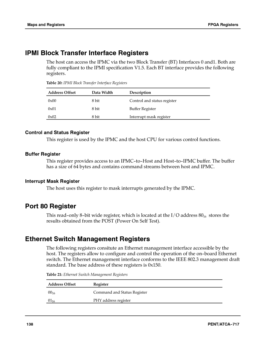
The host can access the IPMC via the two Block Transfer (BT) Interfaces 0 and1. Both are fully compliant to the IPMI specification V1.5. Each BT interface provides the following registers.aa
Table 20: IPMI Block Transfer Interface Registers
Address Offset | Data Width | Description |
0x00 | 8 bit | Control and status register |
0x01 | 8 bit | Buffer Register |
0x02 | 8 bit | Interrupt mask register |
Control and Status Register
This register is used by the IPMC and the host CPU for various control functions.a
Buffer Register
This register provides access to an IPMC−to−Host and Host−to−IPMC buffer. The buffer has a size of 64 bytes and contains command streams between host and IPMC.a
Interrupt Mask Register
The host uses this register to mask interrupts generated by the IPMC.a
Port 80 Register
This read−only 8−bit wide register, which is located at the I/O address 8016astores the results obtained from the POST (Power On Self Test).a
Ethernet Switch Management Registers
The following registers consitute an Ethernet management interface accessible by the host. The registers allow to configure and control the operation of the on−board Ethernet switch. The Ethernet management interface conforms to the IEEE 802.3 management draft standard. The base address of these registers is 0x150.aaa
Table 21: Ethernet Switch Management Registers
Address Offset | Register |
0016 | Command and Status Register |
0116 | PHY address register |
138 | PENT/ATCA−717 |
