Controls, Indicators, and Connectors |
|
| On−Board Connectors | ||||||||||
|
|
|
|
|
|
|
|
|
|
|
|
|
|
|
|
|
|
|
|
|
|
|
|
|
|
|
|
|
|
|
|
|
|
|
|
|
|
|
|
|
|
|
|
|
|
|
|
|
|
|
|
|
|
|
|
|
|
|
|
|
|
|
|
|
|
|
|
|
|
|
|
|
|
|
|
|
|
|
|
|
|
|
|
|
|
|
|
|
|
|
|
|
|
|
|
|
|
|
|
|
|
|
|
|
|
|
|
|
|
|
|
|
|
|
|
|
|
|
|
|
|
|
|
|
|
|
|
|
|
|
|
|
|
|
|
|
|
|
|
|
|
|
|
|
|
|
|
|
|
|
|
|
|
|
|
|
|
|
|
|
|
|
|
|
|
|
|
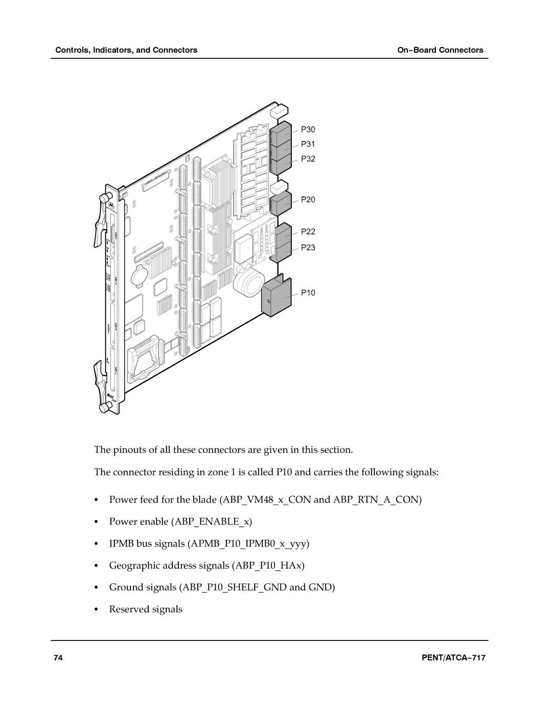
The pinouts of all these connectors are given in this section.a
The connector residing in zone 1 is called P10 and carries the following signals:
SPower feed for the blade (ABP_VM48_x_CON and ABP_RTN_A_CON)
SPower enable (ABP_ENABLE_x)
SIPMB bus signals (APMB_P10_IPMB0_x_yyy)
SGeographic address signals (ABP_P10_HAx)
SGround signals (ABP_P10_SHELF_GND and GND)
SReserved signals
74 | PENT/ATCA−717 |