Installation | Switch Settings |
|
|
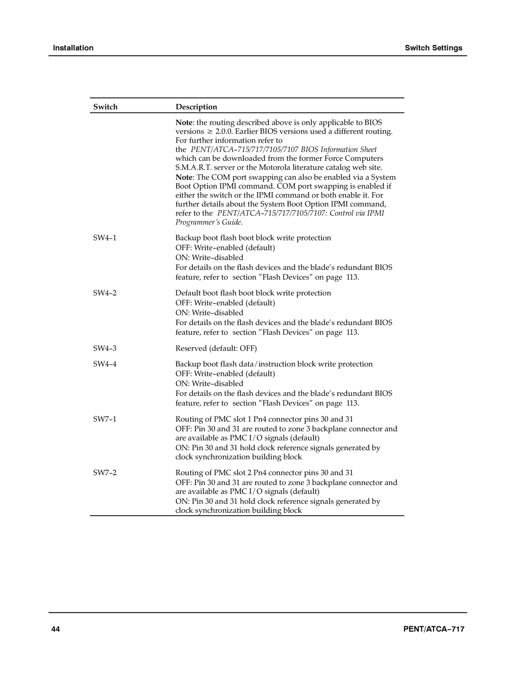
Switch | Description |
| Note: the routing described above is only applicable to BIOS |
| versions w 2.0.0. Earlier BIOS versions used a different routing. |
| For further information refer to |
| theaPENT/ATCA−715/717/7105/7107 BIOS Information Sheeta |
| which can be downloaded from the former Force Computers |
| S.M.A.R.T. server or the Motorola literature catalog web site.a |
| Note: The COM port swapping can also be enabled via a System |
| Boot Option IPMI command. COM port swapping is enabled if |
| either the switch or the IPMI command or both enable it. For |
| further details about the System Boot Option IPMI command, |
| refer to theaPENT/ATCA−715/717/7105/7107: Control via IPMI |
| Programmer’s Guide. |
SW4−1 | Backup boot flash boot block write protection |
| OFF: Write−enabled (default) |
| ON: Write−disableda |
| For details on the flash devices and the blade’s redundant BIOS |
| feature, refer toasection "Flash Devices" on pagea113. |
SW4−2 | Default boot flash boot block write protection |
| OFF: Write−enabled (default) |
| ON: Write−disabled |
| For details on the flash devices and the blade’s redundant BIOS |
| feature, refer toasection "Flash Devices" on pagea113. |
SW4−3 | Reserved (default: OFF) |
SW4−4 | Backup boot flash data/instruction block write protection |
| OFF: Write−enabled (default)a |
| ON: Write−disabled |
| For details on the flash devices and the blade’s redundant BIOS |
| feature, refer toasection "Flash Devices" on pagea113. |
SW7−1 | Routing of PMC slot 1 Pn4 connector pins 30 and 31 |
| OFF: Pin 30 and 31 are routed to zone 3 backplane connector and |
| are available as PMC I/O signals (default) |
| ON: Pin 30 and 31 hold clock reference signals generated by |
| clock synchronization building block |
SW7−2 | Routing of PMC slot 2 Pn4 connector pins 30 and 31 |
| OFF: Pin 30 and 31 are routed to zone 3 backplane connector and |
| are available as PMC I/O signals (default) |
| ON: Pin 30 and 31 hold clock reference signals generated by |
| clock synchronization building block |
44 | PENT/ATCA−717 |