Face Plate | Controls, Indicators, and Connectors |
|
|
USB 1
USB 2
ACT
HDD
U
S
B
1P M C 2
U S B 2
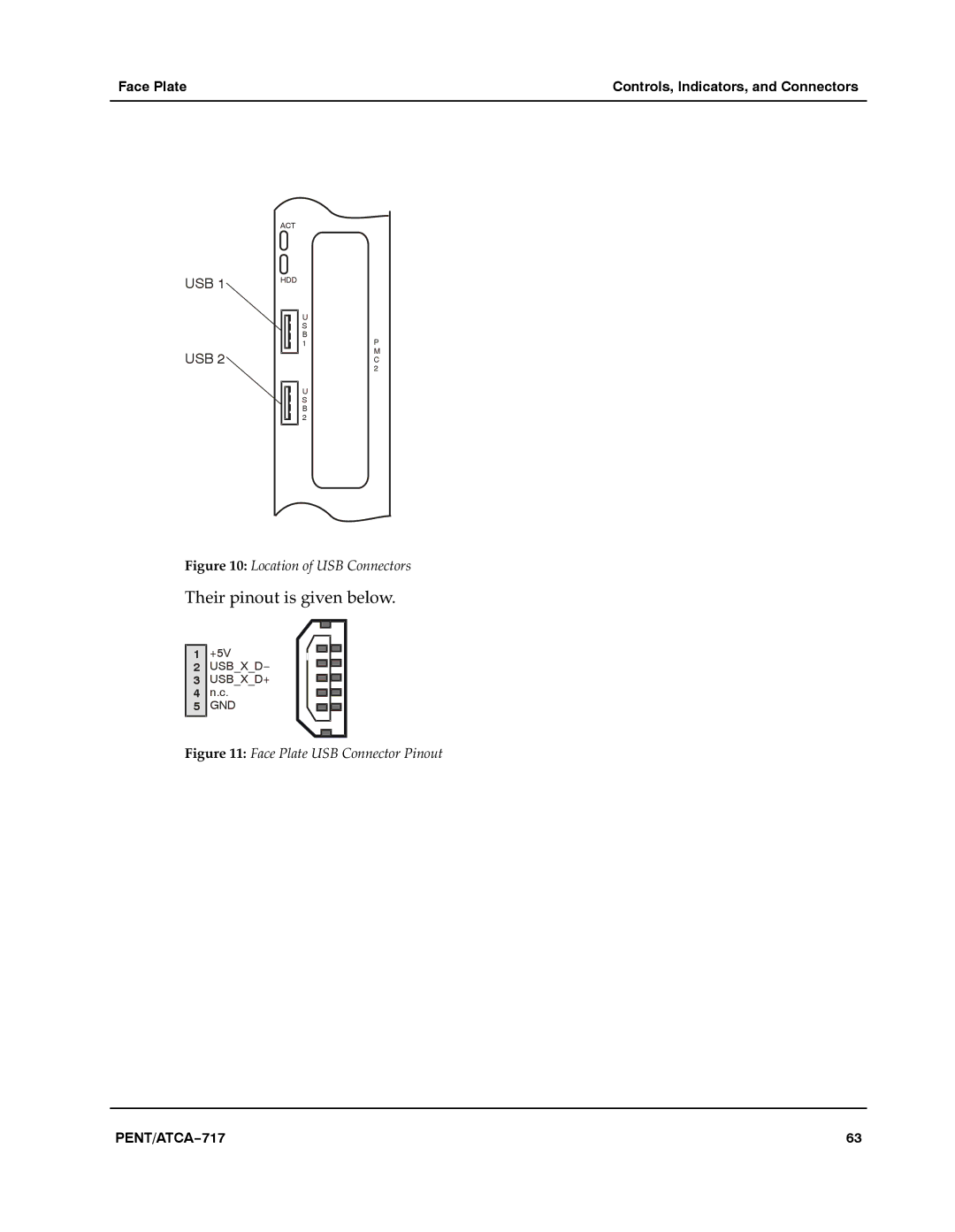
Figure 10: Location of USB Connectors
Their pinout is given below.a
1 | +5V |
2 | USB_X_D− |
3 | USB_X_D+ |
4 | n.c. |
5 | GND |
|
|
Figure 11: Face Plate USB Connector Pinout
PENT/ATCA−717 | 63 |
