Flash Devices | Devices’ Features and Data Paths |
|
|
Flash Devices
The blade provides two redundant boot flash devices: one default boot flash and one backup boot flash. During blade production, both flashes are programmed with identical BIOS images. The presence of two redundant flash devices allows for remotely updating BIOS images from the operating level without interrupting running processes and without being affected by possibly corrupt BIOS images. The backup boot flash, furthermore, can be used to store customized images. Note that in this case the redundant BIOS feature is no longer available.a
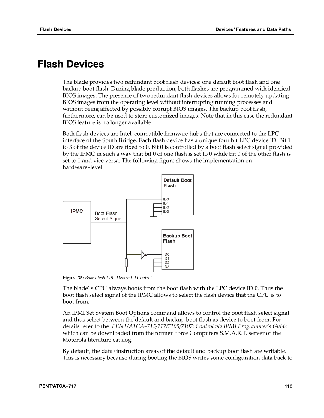
Both flash devices are Intel−compatible firmware hubs that are connected to the LPC interface of the South Bridge. Each flash device has a unique four bit LPC device ID. Bit 1 to 3 of the device ID are fixed to 0. Bit 0 is controlled by a boot flash select signal provided by the IPMC in such a way that bit 0 of one flash is set to 0 while bit 0 of the other flash is set to 1 and vice versa. The following figure shows the implementation on hardware−level.a
IPMC | Boot Flash |
| |
| Select Signal |
Default Boot |
Flash |
ID0 |
ID1 |
ID2 |
ID3 |
Backup Boot |
Flash |
ID0 |
ID1 |
ID2 |
ID3 |
Figure 35: Boot Flash LPC Device ID Control
The blade’ s CPU always boots from the boot flash with the LPC device ID 0. Thus the boot flash select signal of the IPMC allows to select the flash device that the CPU is to boot from.a
An IPMI Set System Boot Options command allows to control the boot flash select signal and thus select between the default and backup boot flash as device to boot from. For details refer to theaPENT/ATCA−715/717/7105/7107: Control via IPMI Programmer’s Guidea which can be downloaded from the former Force Computers S.M.A.R.T. server or the Motorola literature catalog.aaaaaaaa
By default, the data/instruction areas of the default and backup boot flash are writable. This is necessary because during booting the BIOS writes some configuration data back to
PENT/ATCA−717 | 113 |
