On−Board Connectors | Controls, Indicators, and Connectors |
|
|
1 | IDE1_RST# | GND | 2 |
3 | IDE1_D7 | IDE1_D8 | 4 |
5 | IDE1_D6 | IDE1_D9 | 6 |
7 | IDE1_D5 | IDE1_D10 | 8 |
9 | IDE1_D4 | IDE1_D11 | 10 |
11 | IDE1_D3 | IDE1_D12 | 12 |
13 | IDE1_D2 | IDE1_D13 | 14 |
15 | IDE1_D1 | IDE1_D14 | 16 |
17 | IDE1_D0 | IDE1_D15 | 18 |
19 | GND | KEY | 20 |
21 | IDE1_DREQ | GND | 22 |
23 | IDE1_IOW# | GND | 24 |
25 | IDE1_IOR# | GND | 26 |
27 | IDE1_IORDY | IDE1_CSEL | 28 |
29 | IDE1_DACK# | GND | 30 |
31 | IDE1_INT | n.c. | 32 |
33 | IDE1_A1 | IDE1_CBLID# | 34 |
35 | IDE1_A0 | IDE1_A2 | 36 |
37 | IDE1_CS0# | IDE1_CS1# | 38 |
39 | IDE1_DASP# | GND | 40 |
41 | 5V | 5V | 42 |
43 | GND | n.c. | 44 |
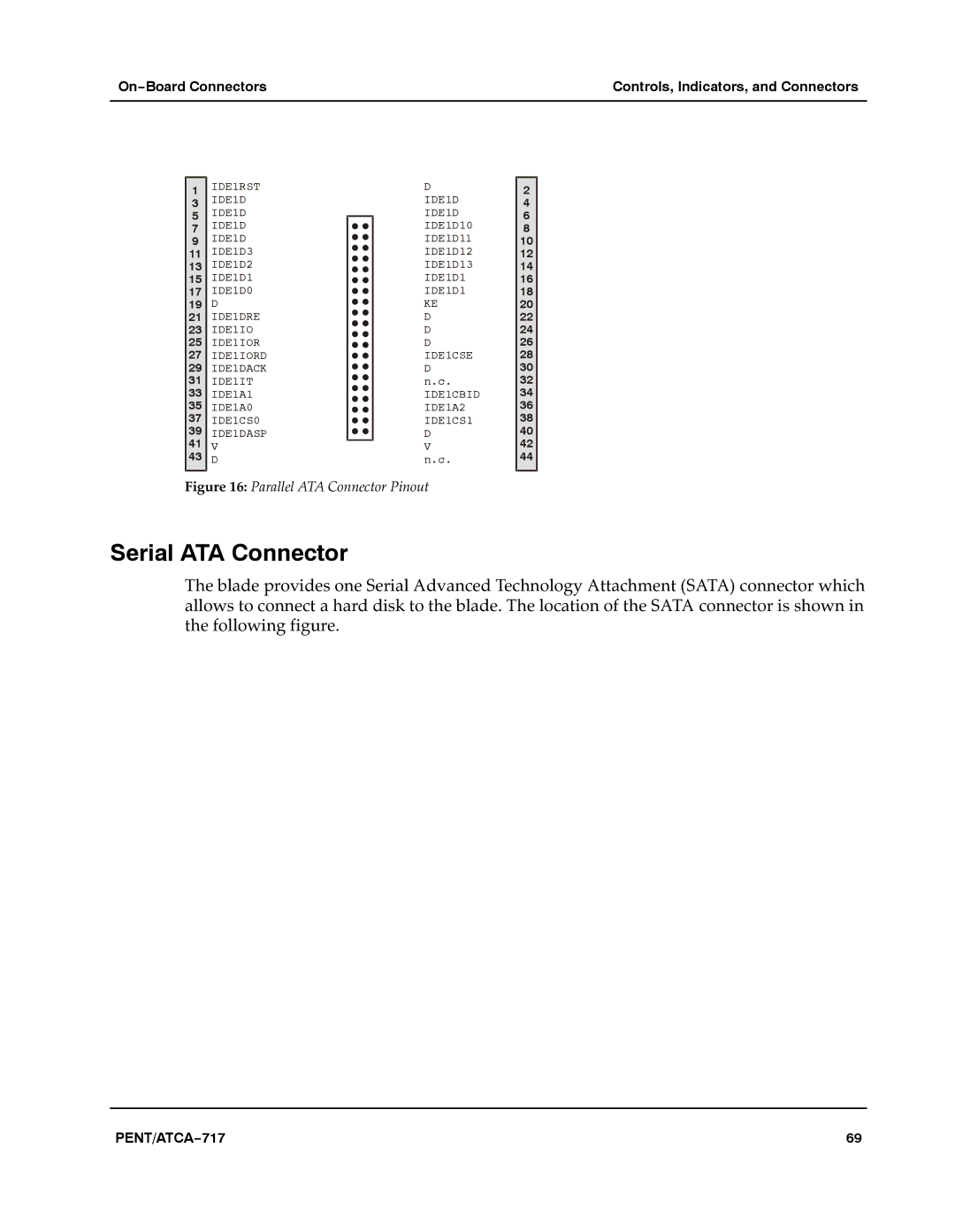
Figure 16: Parallel ATA Connector Pinout
Serial ATA Connector
The blade provides one Serial Advanced Technology Attachment (SATA) connector which allows to connect a hard disk to the blade. The location of the SATA connector is shown in the following figure.aaa
PENT/ATCA−717 | 69 |