Maps and Registers | FPGA Registers |
|
|
SReset mask register (index address 0x01)
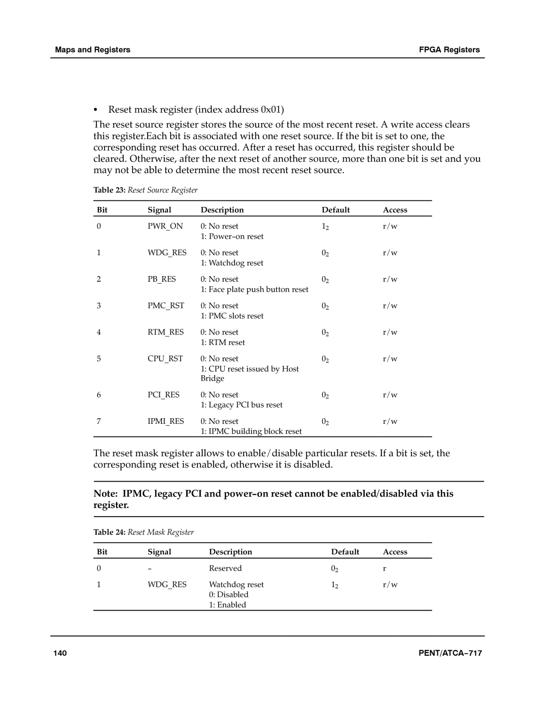
The reset source register stores the source of the most recent reset. A write access clears this register.Each bit is associated with one reset source. If the bit is set to one, the corresponding reset has occurred. After a reset has occurred, this register should be cleared. Otherwise, after the next reset of another source, more than one bit is set and you may not be able to determine the most recent reset source.a
Table 23: Reset Source Register
Bit | Signal | Description | Default | Access |
0 | PWR_ON | 0: No reset | 12 | r/w |
|
| 1: Power−on reset |
|
|
1 | WDG_RES | 0: No reset | 02 | r/w |
|
| 1: Watchdog reset |
|
|
2 | PB_RES | 0: No reset | 02 | r/w |
|
| 1: Face plate push button reset |
|
|
3 | PMC_RST | 0: No reset | 02 | r/w |
|
| 1: PMC slots reset |
|
|
4 | RTM_RES | 0: No reset | 02 | r/w |
|
| 1: RTM reset |
|
|
5 | CPU_RST | 0: No reset | 02 | r/w |
|
| 1: CPU reset issued by Host |
|
|
|
| Bridge |
|
|
6 | PCI_RES | 0: No reset | 02 | r/w |
|
| 1: Legacy PCI bus reset |
|
|
7 | IPMI_RES | 0: No reset | 02 | r/w |
|
| 1: IPMC building block reset |
|
|
The reset mask register allows to enable/disable particular resets. If a bit is set, the corresponding reset is enabled, otherwise it is disabled.a
Note:aIPMC, legacy PCI and power−on reset cannot be enabled/disabled via this register.a
Table 24: Reset Mask Register
Bit | Signal | Description | Default | Access |
0 | − | Reserved | 02 | r |
1 | WDG_RES | Watchdog reset | 12 | r/w |
|
| 0: Disabled |
|
|
|
| 1: Enabled |
|
|
140 | PENT/ATCA−717 |