Configuration-IP Routing Protocols
Restricted rights legend
General
Page
Date Revised Version Reason for revision
Revision History
Revision History
Contents
Index 314
Preface
Series Switch Platforms Series Switch Model Key Features
Related publications
Nortel Ethernet Routing Switch 5500 Series Documentation
Finding the latest updates on the Nortel web site
How to get help
IP addressing
An Introduction to IP Routing Protocols
Network and host boundaries in IP address classes
Subnet addressing
IP routing
IP routing with VLANs
IP routing using VLANs
Multinetting
Network with Multinetting
Proxy ARP UDP broadcast
Brouter port
Setting IP routing
Layer 2 versus Layer 3 mode
Management Vlan
Routing and management
End
Address Resolution Protocol ARP
Step Action
Proxy ARP Operation
Proxy Address Resolution Protocol Proxy ARP
Static routes
RIP operation
Non-local static routes
Routing Information Protocol RIP
An Introduction to IP Routing Protocols
RIP hop counts
RIP metrics
RIP Send and Receive Modes
RIP send and receive modes Send Mode Description Result
Receive Result Mode
Overview
Limitations
Open Shortest Path First Ospf protocol
Ospf routing algorithm
Benefits
Ospf router types Router Type Description
Ospf router types
Ospf host route
Host route in LSA
Ospf Enhancements
Following is an example for deleting a host route
R3config-router#
Ospf virtual link
Consider the following situation
Virtual link diagram
Example Configuration
Creating auto virtual link
R1 config-router#auto-vlink
R3config#show ip ospf
R1 config-router#no auto-vlink
Following is an example for deleting an auto virtual link
Deleting auto virtual link
Route policies
Announce Out Policies
Accept In Policies
Redistribution Policies
Prefix Lists
Virtual Router Redundancy Protocol Vrrp
UDP broadcast forwarding
Equal Cost MultiPath Ecmp
Summary of Dhcp relay operation
Differences between Dhcp and BootP
Forwarding Dhcp packets
Multiple BootP-DHCP servers
Dhcp operation
Forwarding Dhcp packets
To set DHCP, take the following steps
Setting Dhcp
Multiple BootP/DHCP servers
Dhcp relay
Global Dhcp relay commands Command Description
Dhcp relay forward path commands Command Description
Interface Dhcp relay commands Command Description
Automatic router ID change
Avoiding duplicate IP addresses
IP blocking
Igmp snooping
IP multicast propagation with Igmp routing
Series switch filtering IP multicast streams 1
, 5500 Series switch filtering IP multicast streams 1 of 2
Igmp snooping configuration rules
Series switch filtering IP multicast streams 2
An Introduction to IP Routing Protocols
Global IP routing configuration
IP Routing Configuration and Management
Basic Ospf configuration
Open Shortest Path First Ospf initial configuration
Return to Global Configuration mode
Enable Ospf in Vlan
Basic Asbr configuration
Assign an IP address to Vlan
Configuring Ecmp for Ospf
Log into the Ospf router configuration mode
Enable Asbr functionality
Ip routing command
IP configuration commands
No ip routing command
Ip blocking-mode command
Ip address command
Interface vlan command
Layer 3 routable VLANs
Interface vlan 1
Adding secondary IP interfaces Step Action
No ip address command
Define a secondary IP interface on the Vlan
No ip address A.B.C.D W.X.Y.Z
Remove the primary IP interface from the Vlan
Show vlan ip command
Show vlan ip command shows routable Vlan configurations
Show ip route static command
Static route commands
Show ip route command
Syntax for the show vlan ip command is
Ip route command
Show ip route summary command
Show ip route summary
Ip route A.B.C.D W.X.Y.Z O.P.Q.R
Ip route enable command
No ip route command
Ip route A.B.C.D W.X.Y.Z O.P.Q.R enable
No ip route A.B.C.D W.X.Y.Z O.P.Q.R
Traceroute command
Ip route disable command
Ip route enable parameters Parameter Description
Ip route A.B.C.D W.X.Y.Z O.P.Q.R disable
Ip route weight command
Show arp command
Address Resolution Protocol ARP commands
Show ip arp command
Show arp-table A.B.C.D
Ip arp command
Show ip arp static command
Show ip arp static
Ip arp A.B.C.D aabbccddeeff unit / port vid
Ip arp timeout command
No ip arp command
Proxy ARP commands
Ip arp-proxy command
Show ip arp-proxy interface command
Default ip arp-proxy command
Routing Information Protocol RIP commands
Router rip enable command
Network command
Router rip command
No network command
Timers basic holddown command
Ip rip advertise-when-down command
Timers basic timeout command
Timers basic update command
Ip rip auto-aggregation command
No ip rip advertise-when-down command
No ip rip auto-aggregation command
Ip rip cost command
No ip rip default-listen command
Ip rip default-listen command
Ip rip default-supply command
No ip rip default-supply command
Ip rip in-policy command
Ip rip holddown command
No ip rip in-policy command
Ip rip listen command
Ip rip out-policy command
No ip rip listen command
No ip rip out-policy command
Ip rip poison command
Ip rip proxy-announce command
No ip rip poison command
No ip rip proxy-announce command
Ip rip receive command
No ip rip supply command
Ip rip send command
Ip rip supply command
Ip rip triggered command
Ip rip timeout command
No ip rip triggered command
Show ip rip command
Default default-metric command
Default router rip command
Default timers basic holddown command
Default timers basic timeout command
Default-metric command
Default timers basic update command
Default ip rip advertise-when-down command
Default ip rip auto-aggregation command
Default ip rip default-listen command
Default ip rip cost command
Default ip rip default-supply command
Default ip rip enable command
Default ip rip in-policy command
Default ip rip holddown command
Default ip rip listen command
Default ip rip out-policy command
Default ip rip receive command
Default ip rip proxy-announce command
Default ip rip send command
Default ip rip supply command
Default ip rip triggered command
Default ip rip timeout command
Open Shortest Path First Ospf commands
Ip ospf apply accept command
Ip ospf apply redistribute rip command
Ip ospf apply redistribute direct command
Ip ospf apply redistribute static command
Ip ospf spf-run command
No router ospf enable command
Router ospf enable command
Router ospf command
Default router ospf command
Area command
No accept adv-rtr command
No accept adv-rtr routeripaddress enable
Accept adv-rtr parameters Parameter Description
Area parameters
No area command
Area command is executed in the Router Configuration mode
No as-boundary-router command
As-boundary-router command
Default-cost ethernet command
No area command is executed in the Router Configuration mode
Default-cost ten-gig-ethernet command
Default-cost fast-ethernet command
Default-cost gig-ethernet command
Following table describes the parameters of this command
Host-route command
No host-route command
No redistribute command
Redistribute command
Parameters for this command are listed below
Redistribute routetype enable route-policy policyname
No rfc1583-compatibility command
Rfc1583-compatibility command
Router-id command
No router-id command
Area virtual-link command
Trap command
No trap command
Word
No area virtual-link command
No area virtual-link A.B.C.D. W.X.Y.Z authentication- key
Area virtual-link message-digest-key command
No area virtual-link message-digest-key command
Ip ospf advertise-when-down command
Auto-vlink command
No auto-vlink command
Ip ospf authentication-key command
Ip ospf area command
Ip ospf authentication-type command
Ip ospf cost command
Ip ospf hello-interval command
Ip ospf dead-interval command
Ip ospf mtu-ignore command
Ip ospf network command
Ip ospf retransmit-interval command
Ip ospf primary-md5-key command
Ip ospf priority command
Ip ospf message-digest-key command
Ip ospf transmit-delay command
Ospf show commands
Syntax of the ip ospf message-digest-keycommand is
Clear ip ospf counters command
Command Description
Route policy commands
Clear ip ospf counters command
Ip prefix-list command
Clear ip ospf counters
Route-map parameters Field Description
Route-map command
Ip prefix-list parameters Parameter Description
Ip rip out-policy rmapname
Ip rip in-policy rmapname
Router vrrp enable command
Virtual Router Redundancy Protocol Vrrp commands
No router vrrp enable command
Router vrrp command
Send-trap enable command
No ping-virtual-address enable command
No send-trap enable command
Ip vrrp address command
Ip vrrp adver-int command
No ip vrrp address command
Ip vrrp action command
No ip vrrp backup-master command
Ip vrrp backup-master command
Ip vrrp critical-ip command
No ip vrrp critical-ip command
Ip vrrp enable command
Ip vrrp critical-ip-addr command
No ip vrrp enable command
Ip vrrp fast-adv command
Ip vrrp holddown-timer command
No ip vrrp fast-adv command
Ip vrrp fast-adv-int command
Show ip vrrp command
Ip vrrp priority command
Equal Cost MultiPath Ecmp commands
Rip maximum-path command
Show ecmp command
Ospf maximum-path command
Maximum-path command
Brouter command
Brouter port commands
No brouter command
No brouter port brouterport routing enable
UDP broadcast forwarding commands
Show brouter command
Ip forward-protocol udp command
Show brouter command is executed in the User Exec mode
Ip forward-iprotocol udp command interface mode
Clear ip forward-protocol udp counters command
Where the parameter 1-4094 specifies the Vlan ID
Clear ip forward-protocol udp counters
Ip dhcp-relay command
Dhcp relay commands
No ip dhcp-relay command
To set DHCP, perform the following procedure
Show ip dhcp-relay fwd-path command
Show ip dhcp-relay counters command
Ip dhcp-relay fwd-path command
Syntax for the show ip dhcp-relayfwd-pathcommand is
Ip dhcp-relay fwd-path disable command
Ip dhcp-relay fwd-path enable command
Syntax for the ip dhcp-relayfwd-path enable command is
Dhcp feature is enabled by default
Show vlan dhcp-relay command
No ip dhcp-relay fwd-path command
Dhcp relay feature is enabled by default
No ip dhcp-relay fwd-path A.B.C.D O.P.Q.R
Ip dhcp-relay parameters Parameter Description
Ip dhcp-relay broadcast command
Ip dhcp-relay min-sec 0-65535 mode bootp dhcp bootpdhcp
Address Resolution Protocol ARP configuration
No ip dhcp-relay broadcast command
Syntax for the no ip dhcp-relay broadcast command is
Ip dhcp-relay broadcast
This section contains the following topics
Changing the default ARP aging time
Adding a static ARP entry to a Vlan
Deleting a static ARP entry
Adding a static ARP entry to a brouter port
Routing Information Protocol RIP configuration
RIP configuration tasks
Disable Supply RIP Updates, if required
Enable RIP
Disable Listen for RIP Updates, if required
Configure the interface, assign an IP address and add ports
10 Configure send mode parameters
Enable Triggered Updates, if required
11 Configure receive mode parameters
Enable poison reverse
RIP configuration example
Configuring RIP
Assign the IP address 10.1.30.2/24 to Vlan
Assign the IP address 10.1.20.2/24 to Vlan
5530-24TFDconfig-if#ip rip listen disable
Enable RIP on the interface
Enable IP routing and RIP globally
Configuring RIP version
RIPv2 configuration example
Using RIP accept policies
Accept policy configuration
Add the route policy created in to both RIP core ports
Using RIP announce policies
Configure the IP prefix list named Prefix2 with the IP address
Open Shortest Path First Ospf configuration
5530-24TFDconfig# route-map rippol2 1 match network Prefix2
Configuring an IP Ospf interface
Ospf interface example topology
Ospf security
IP Routing Configuration and Management
Configure MD5 authentication on R2
Configure MD5 authentication on R1
Configuring Ospf network types
MD5 configuration example
Ospf network example
Configuring Ospf areas
Ospf normal area
5530-24TFDconfig-router# as-boundary-router enable
Ospf stub area
Ospf stub area example
Enable Ospf on R1
End
Nssa configuration example
Enable RIP globally and configure the RIP version 2 interface
Apply the RipDist route policy to RIP Out Policy
ABR configuration example
Configuring Area Border Routers ABR
End
0.2 172.3.0.0/16 Summary Link Summarize 100
Configuring Autonomous System Border Routers Asbr
Area ID Range Subnet/Mask Range Type
Asbr distribution example
Configure the RIP interface for RIP version 2 mode only
5530-24TFDconfig# ip prefix-list default 0.0.0.0/0
Controlling Nssa external route advertisements
External route advertisement example
Enable Ospf
Apply route policy to RIP Out Policy
Multi-area complex example
Configuring a multi-area complex
IP Routing Configuration and Management
IP routing configuration examples
IP Routing Configuration and Management
R2 configuration commands
IP Routing Configuration and Management
IP routing configuration examples
STP Phase
R3 configuration commands
IP routing configuration examples
IP Routing Configuration and Management
IP routing configuration examples
IP Routing Configuration and Management
IP routing configuration examples
IP Routing Configuration and Management
R4 configuration commands
IP Routing Configuration and Management
IP routing configuration examples
R5 configuration commands
IP routing configuration examples
IP Routing Configuration and Management
Show ip ospf
Router R1 Status show vlan
Show vlan ip
Show ip ospf neighbor
Show ip ospf area
Router R2 Status show vlan
Show ip route
100 10100 10.1.1.17 255.255.255.252
IfIndex Address Mask MacAddress
10001 203.203.100.53 255.255.255.0
Show ip ospf interface
Router R3 Status Show vlan
Show ip rip interface
Show ip rip
Show ip ospf redistribute
Show route-map detail
172.1.1.1 203.203.100.52 IP Address Holddown
Type Allow True
IP routing configuration examples
Nbr Router ID Nbr IP Address Pri State RetransQLen Perm
Router R4 Status Show vlan
IP Routing Configuration and Management
Router R5 Status
Port Members 1000 Vlan #1000 Port None 0x0000 Yes
Yes Port Members 100 Vlan #100 Port None 0x0000
IP routing configuration examples
Diagnosing neighbor state problems
Accessed by using the show ip ospf neighbor command
Virtual Router Redundancy Protocol Vrrp configuration
Vrrp example topology
Configuring normal Vrrp operation
Configure an Ospf interface for Vlan
Configure Vlan 2 on router R1 Create Vlan 2 on router R1
Configure the ports for Vlan 2 on R1
Configure Vlan 2 on router R2 Create Vlan 2 on router R2
Configure the ports for Vlan 3 on R1
Configure Vlan 3 on router R2
Configure the ports for Vlan 2 on R2
End
Vlan Configuration for Router R2
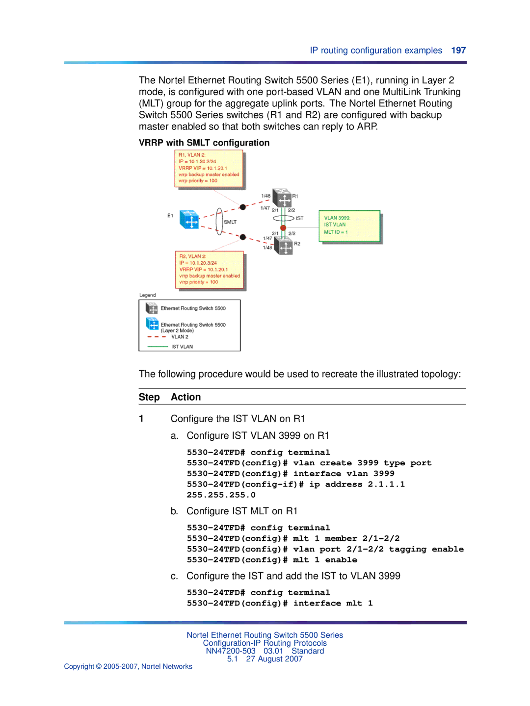
Configuring Vrrp with Smlt
Configure the IST Vlan on R1 Configure IST Vlan 3999 on R1
5530-24TFD# config terminal 5530-24TFDconfig# interface mlt
Configure IST MLT on R1
Configure the IST and add the IST to Vlan
5530-24TFDconfig-if# ist enable peer-ip 2.1.1.2 vlan
Enable Ospf interface on Vlan 2 of R1
Create IP address for Vlan
Create Smlt on R1
Configure IST MLT on R2
Enable Ospf interface for Vlan 2 on R2
Configure an IST peer for R2 and add the IST to Vlan
Create an IP address for Vlan
Configure Vrrp VIP address for Vlan 2 on R2
Configuration for R2
Vrrp with SLT configuration
Mlt spanning-tree 2 stp all learning disable
Configuring Vrrp with SLT
Configuration for R2
Ecmpindex = R2 % ecmpcount +
R1 = CRC32 SIP, DIP
R2 = R1 & 0x1FThe Least Significant 5 bits are selected
Ecmp configuration example
5530-24TFDconfig#ospf maximum-path
Displaying the IP routing table
5530-24TFD# show ecmp Protocol MAX-PATH Static1 Rip2 Ospf4
Displaying global Ecmp configuration
IP dialog Globals tab
Creating a Layer 3 routable Vlan
IP Vlan screen
Following table describes the IP Address tab fields
IP Address tab fields Field Description
Insert IP Address screen
Globals tab
IP routing
Click Insert
IP screen
Addresses tab
Addresses tab
Globals tab fields Field Description
IP dialog- Routes tab
Routes tab
Addresses tab fields Field Description
Routes tab fields Field Description
Filtering route information
Filter dialog fields Field Description
Click Filter
Static Routes tab
Tab will now be filtered on the criteria specified
Static Routes tab
Insert Static Route fields
ARP tab
Field Description
ARP tab
Click Insert. The ARP tab is displayed with the new entry
ARP Interfaces tab
Insert ARP Entry screen
Insert ARP Entry fields Field Description
IP screen ARP Interfaces tab
ARP Inspection Vlan tab
ARP Interfaces tab fields Field Description
ARP Inspection-VLAN tab
ARP Inspection-port tab
ARP Inspection port tab
TCP tab fields Field Description
TCP tab
TCP tab
UDP Listeners tab
TCP Connections tab
TCP Connections tab
TCP Connections tab fields Field Description
UDP Listeners tab fields Field Description
Ecmp tab
UDP Listeners tab
Ecmp tab fields Field Description
Global RIP configuration
IP dialog Ecmp tab
RIP dialog Globals tab
Interface tab fields Field Description
RIP interface configuration
RIP dialog Interface tab
Interface Advance tab fields Field Description
Advanced RIP interface configuration
RIP dialog Interface Advance tab
Stats tab
RIP Statistics
RIP Stats Graph dialog
Vlan RIP configuration
Stats tab fields Field Description
RIP tab fields Field Description
IP Vlan screen RIP tab
General tab fields Field Description
Global Ospf configuration
Ospf dialog General tab
Field Description
Ospf dialog Areas tab
Ospf area configuration
Areas tab fields Field Description
Ospf area creation
To delete an Ospf area, use the following procedure
Ospf area deletion
Deleting an Ospf area
Stub Area Metrics tab fields
Stub Area Metrics configuration
Ospf dialog Stub Area Metrics tab
Interfaces tab fields Field Description
Interface configuration
Ospf dialog Interfaces tab
Field Description
Ospf dialog If Metrics tab
Interface Metric configuration
Ospf dialog Neighbors tab
Neighbor information
If Metrics tab fields Field Description
Neighbor tab fields Field Description
Click Refresh to update the information
Virtual interface information
Virtual Interface fields Field Description
Virtual If tab
Creating an Ospf virtual interface Step Action
Virtual interface creation
Enter the information in the fields on the Virtual If window
Click Insert. The OSPF, Insert Virtual If dialog opens
Virtual interface tab
Insert virtual interface dialog
Automatic Virtual Link creation
Virtual interface deletion
Deleting an Ospf virtual interface Step Action
Creating an automatic Virtual Link Step Action
Deselect the AutoVirtLinkEnable box
Check the AutoVirtLinkEnable box
Automatic Virtual Link Deletion
Virtual neighbors information
Virtual Neighbors tab fields Field Description
Virtual Neighbors tab
Ospf Hosts information
To create an Ospf host, use the following procedure
Ospf Host creation
Hosts tab
Ospf Host deletion
To delete an Ospf host, use the following procedure
Creating an Ospf host Step Action
Deleting an Ospf host Step Action
Link State Database fields Field Description
Link State Database information
Ospf dialog Link State Database tab
Ext. Link State Database fields Field
External Link State Database information
Ospf dialog Ext. Link State Database tab
Area Aggregate configuration
Area Aggregate tab fields Field Description
Ospf dialog Area Aggregate tab
Area Aggregate creation
To create a new Ospf area aggregate, follow this procedure
Insert Area Aggregate dialog
Insert Area Aggregate dialog fields Field Description
Deleting an Ospf area aggregate Step Action
Area Aggregate deletion
Ospf redistribution configuration
Redistribution creation
To create a new redistribution entry, follow this procedure
Ospf dialog Redistribute tab
Redistribute tab fields Field Description
Insert Redistribute dialog fields Field Description
Redistribution deletion
Insert Redistribute dialog
Deleting a redistribution entry Step Action
Message Digest information
Ospf dialog Message Digest tab
Message Digest tab fields Field Description
Message Digest creation
Click Refresh to update the displayed information
Insert Message Digest dialog
Insert Message Digest dialog fields Field Description
Virtual If Message Digest information
Message Digest deletion
Deleting an Ospf message digest entry Step Action
Virtual If Message Digest tab
Virtual If Message Digest fields Field Description
Virtual If Message Digest creation
Creating a Virtual If Message Digest entry Step Action
Ospf statistics
Virtual If Message Digest deletion
Enter the information in the fields provided Click Insert
Deleting a Virtual If Message Digest entry Step Action
Ospf
Ospf dialog Stats tab
Vlan Ospf statistics
Ospf Stats tab fields Field Description
Ospf Stats tab
Prefix List configuration
Prefix List creation
To create a new prefix list, follow this procedure
Policy dialog Prefix List tab
Prefix List tab fields Field Description
Prefix List deletion
To delete a prefix list, use the following procedure
Deleting a Prefix List Step Action
Insert Prefix List dialog
Route Policy tab fields Field Description
Route Policy configuration
Policy dialog Route Policy tab
IP Routing Configuration and Management
Route Policy creation
To create a new route policy, follow this procedure
Insert Route Policy fields Field Description
Insert Route Policy dialog
IP routing configuration using the Java Device Manager
Deleting a route policy Step Action
To delete a route policy, use the following procedure
Route policy deletion
Ospf Accept Policy configuration
Applying Ospf policies
Policy dialog Applying Policy tab
Applying Policy tab fields Field Description
Ospf Accept Policy creation
To create a new Ospf accept policy, follow this procedure
Policy dialog Ospf Accept tab
Ospf Accept tab fields Field Description
Deleting an Ospf accept policy Step Action
Ospf Accept Policy deletion
Insert Ospf Accept dialog
Insert Ospf Accept fields Field Description
RIP In/Out Policy tab fields Field Description
RIP In and Out Policy configuration
Policy dialog RIP In/Out Policy tab
Vrrp dialog Globals tab
Global Vrrp configuration
Vrrp dialog Interface Address tab
Vrrp interface creation
Vrrp Interface deletion
To delete a Vrrp interface, use the following procedure
Deleting a Vrrp interface Step Action
Insert Interface Address dialog
Vrrp dialog Interfaces tab
Vrrp interface management
IP routing configuration using the Java Device Manager
Vrrp Stats dialog
Graphing Vrrp interface information
Type field
Viewing general Vrrp statistics
Vrrp Stats fields Field Description
Vrrp dialog Stats tab
Select a port on the Device Manager Front Panel view
Ecmp configuration
Configuration and management of Brouter ports
Port dialog IP Address tab
To create a new brouter port, use the following procedure
Creating a Brouter port
Deleting a Brouter port
To delete a brouter port, use the following procedure
Insert IP Address dialog
Insert IP Address dialog fields Field Description
Insert Protocols dialog
UDP protocol configuration
UDP Forward dialog Protocols tab
UDP Forward dialog Forwardings tab
UDP forwarding configuration
Insert Protocols dialog fields Field Description
Deleting a UDP forwarding Step Action
UDP forwarding deletion
Insert Forwardings dialog
Insert Forwardings dialog fields Field Description
UDP forwarding list creation
UDP forwarding list configuration
UDP Forward dialog Forwarding Lists tab
Forwarding Lists tab fields Field Description
Deleting a UDP forwarding list Step Action
UDP forwarding list deletion
Select the Forwarding Lists tab
Insert Forwarding Lists dialog
Select an Id to delete Click Delete
Configuring UDP broadcast interfaces
UDP Forward dialog Broadcast Interfaces tab
Broadcast Interface tab fields Field Description
Insert Broadcast Interfaces dialog
UDP broadcast interface creation
Deleting a UDP broadcast interface
UDP broadcast interface deletion
Dhcp configuration
Insert Broadcast Interfaces dialog fields Field Description
Creating a Dhcp entry Step Action
To configure a Dhcp entry, use the following procedure
Dhcp Relay tab
Insert Dhcp Relay
To enable Dhcp Snooping, use the following procedure
To delete a Dhcp entry, use the following procedure
Dhcp Snooping
Dhcp Snooping Vlan
Dhcp Snooping-VLAN tab
Dhcp Snooping port
Dhcp Snooping-port tab
Dhcp bindings
Dhcp Bindings
IP Source Guard port
IP Source Guard-addresses tab
IP Source Guard addresses
IP Source Guard-port tab
Following table describes the Dhcp tab fields
Vlan Dhcp configuration
Dhcp tab fields
Dhcp tab fields Fields Description
Fields Description
Make changes as necessary in the fields provided Click Apply
IP Routing Configuration and Management
Vlan Snoop tab
Configuring Igmp snooping using the Java Device Manager
Vlan Snoop tab fields Field Description
Enabling Igmp Snooping for a Vlan
308 Configuring Igmp snooping using the Java Device Manager
Igmp Configuration screen
Configuring Igmp using Web-based management
Igmp Vlan Configuration screen
Igmp Vlan Setting fields Field Description
Configuring Igmp using the Web-based Management Interface
Igmp Multicast Group Membership window
Vlan Configuration screen reopens and the settings are saved
Click Submit
Multicast Group
Index
Ospf
Non-local static routes
Index
Page
Configuration-IP Routing Protocols