B Connectors and Allocation
Signal
This section describes the parallel interface


 Shape of the connector
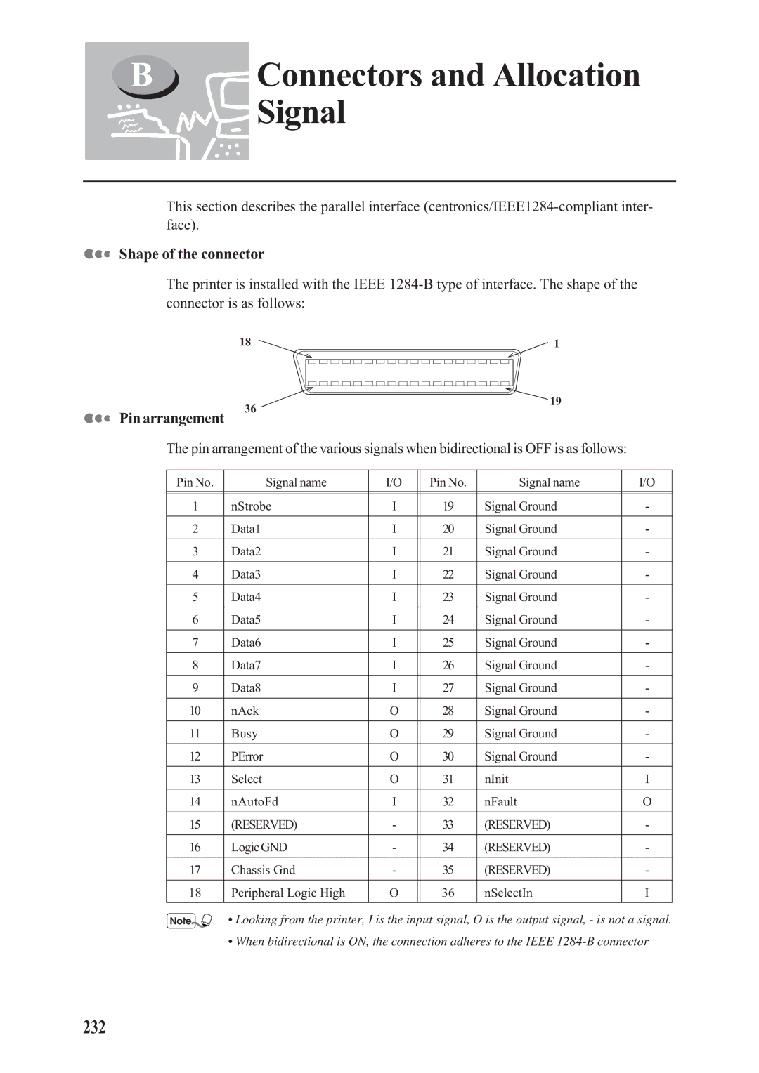
The printer is installed with the IEEE
18 | 1 |


 Pin arrangement
36
19
The pin arrangement of the various signals when bidirectional is OFF is as follows:
Pin No. | Signal name | I/O | Pin No. | Signal name | I/O |
|
|
|
|
|
|
|
|
|
|
|
|
1 | nStrobe | I | 19 | Signal Ground | - |
|
|
|
|
|
|
2 | Data1 | I | 20 | Signal Ground | - |
|
|
|
|
|
|
3 | Data2 | I | 21 | Signal Ground | - |
|
|
|
|
|
|
4 | Data3 | I | 22 | Signal Ground | - |
|
|
|
|
|
|
5 | Data4 | I | 23 | Signal Ground | - |
|
|
|
|
|
|
6 | Data5 | I | 24 | Signal Ground | - |
|
|
|
|
|
|
7 | Data6 | I | 25 | Signal Ground | - |
|
|
|
|
|
|
8 | Data7 | I | 26 | Signal Ground | - |
|
|
|
|
|
|
9 | Data8 | I | 27 | Signal Ground | - |
|
|
|
|
|
|
10 | nAck | O | 28 | Signal Ground | - |
|
|
|
|
|
|
11 | Busy | O | 29 | Signal Ground | - |
|
|
|
|
|
|
12 | PError | O | 30 | Signal Ground | - |
|
|
|
|
|
|
13 | Select | O | 31 | nInit | I |
|
|
|
|
|
|
14 | nAutoFd | I | 32 | nFault | O |
|
|
|
|
|
|
15 | (RESERVED) | - | 33 | (RESERVED) | - |
|
|
|
|
|
|
16 | LogicGND | - | 34 | (RESERVED) | - |
|
|
|
|
|
|
17 | Chassis Gnd | - | 35 | (RESERVED) | - |
|
|
|
|
|
|
18 | Peripheral Logic High | O | 36 | nSelectIn | I |
|
|
|
|
|
|
• Looking from the printer, I is the input signal, O is the output signal, - is not a signal.
• When bidirectional is ON, the connection adheres to the IEEE