| Optional Equipment |
|
|
EN 90
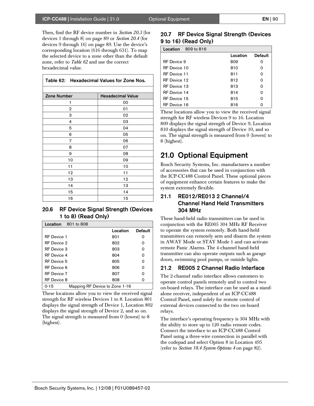
Then, find the RF device number in Section 20.3 (for devices 1 through 8) on page 89 or Section 20.4 (for devices 9 through 16) on page 89. Use the device’s corresponding location (616 through 631). To map the selected device to a zone other than the default zone, refer to Table 62 and use the correct hexadecimal value.
Table 62: Hexadecimal Values for Zone Nos.
Zone Number | Hexadecimal Value |
1 | 00 |
2 | 01 |
3 | 02 |
|
|
4 | 03 |
5 | 04 |
|
|
6 | 05 |
7 | 06 |
8 | 07 |
|
|
9 | 08 |
10 | 09 |
11 | 10 |
|
|
12 | 11 |
13 | 12 |
|
|
14 | 13 |
|
|
15 | 14 |
16 | 15 |
|
|
20.6RF Device Signal Strength (Devices 1 to 8) (Read Only)
Location 801 to 808
| Location | Default |
RF Device 1 | 801 | 0 |
RF Device 2 | 802 | 0 |
RF Device 3 | 803 | 0 |
RF Device 4 | 804 | 0 |
RF Device 5 | 805 | 0 |
RF Device 6 | 806 | 0 |
RF Device 7 | 807 | 0 |
RF Device 8 | 808 | 0 |
|
|
|
Mapping RF Device to Zone |
|
These locations allow you to view the received signal strength for RF wireless Devices 1 to 8. Location 801 displays the signal strength of Device 1, Location 802 displays the signal strength of Device 2, and so on.
The signal strength is measured from 0 (lowest) to 8 (highest).
20.7RF Device Signal Strength (Devices 9 to 16) (Read Only)
Location 809 to 816
| Location | Default |
RF Device 9 | 809 | 0 |
RF Device 10 | 810 | 0 |
RF Device 11 | 811 | 0 |
RF Device 12 | 812 | 0 |
RF Device 13 | 813 | 0 |
RF Device 14 | 814 | 0 |
RF Device 15 | 815 | 0 |
RF Device 16 | 816 | 0 |
These locations allow you to view the received signal strength for RF wireless Devices 9 to 16. Location
809 displays the signal strength of Device 9, Location 810 displays the signal strength of Device 10, and so on. The signal strength is measured from 0 (lowest) to 8 (highest).
21.0 Optional Equipment
Bosch Security Systems, Inc. manufactures a number of accessories that can be used in conjunction with the
21.1RE012/RE013 2 Channel/4 Channel Hand Held Transmitters 304 MHz
These
21.2RE005 2 Channel Radio Interface
The
The interface’s operating frequency is 304 MHz with the ability to store up to 120 radio remote codes. Connect the interface to an