| Programming Sheets |
|
|
EN 108
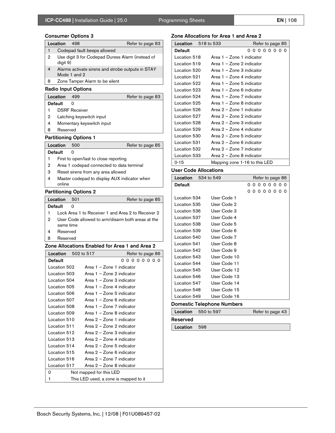
Consumer Options 3
Location | 498 | Refer to page 83 | |
1 | Codepad fault beeps allowed |
| |
2 | Use digit 3 for Codepad Duress Alarm (instead of | ||
| digit 9) |
| |
4 | Alarms activate sirens and strobe outputs in STAY | ||
| Mode 1 and 2 |
| |
8 | Zone Tamper Alarm to be silent |
| |
|
|
|
|
Radio Input Options
Location | 499 | Refer to page 83 | |
Default | 0 |
| |
1 | DSRF Receiver |
| |
2 | Latching keyswitch input |
| |
4 | Momentary keyswitch input |
| |
8 | Reserved |
| |
Partitioning Options 1
Location | 500 | Refer to page 85 | |
Default | 0 |
| |
1 | First to open/last to close reporting |
| |
2 | Area 1 codepad connected to data terminal | ||
3 | Reset sirens from any area allowed |
| |
4 | Master codepad to display AUX indicator when | ||
| online |
|
|
|
|
|
|
Partitioning Options 2
Location | 501 | Refer to page 85 | |
Default | 0 |
| |
1 | Lock Area 1 to Receiver 1 and Area 2 to Receiver 2 | ||
2 | User Code allowed to arm/disarm both areas at the | ||
| same time |
| |
4 | Reserved |
| |
8 | Reserved |
| |
|
|
|
|
Zone Allocations Enabled for Area 1 and Area 2
Location | 502 to 517 | Refer to page 86 | |
Default |
|
| 0 0 0 0 0 0 0 0 |
Location 502 | Area 1 – Zone 1 indicator | ||
Location 503 | Area 1 – Zone 2 indicator | ||
Location 504 | Area 1 – Zone 3 indicator | ||
Location 505 | Area 1 – Zone 4 indicator | ||
Location 506 | Area 1 – Zone 5 indicator | ||
Location 507 | Area 1 – Zone 6 indicator | ||
Location 508 | Area 1 – Zone 7 indicator | ||
Location 509 | Area 1 – Zone 8 indicator | ||
Location 510 | Area 2 – Zone 1 indicator | ||
Location 511 | Area 2 – Zone 2 indicator | ||
Location 512 | Area 2 – Zone 3 indicator | ||
Location 513 | Area 2 – Zone 4 indicator | ||
Location 514 | Area 2 – Zone 5 indicator | ||
Location 515 | Area 2 – Zone 6 indicator | ||
Location 516 | Area 2 – Zone 7 indicator | ||
Location 517 | Area 2 – Zone 8 indicator | ||
0 | Not mapped for this LED |
| |
1 | This LED used, a zone is mapped to it | ||
Zone Allocations for Area 1 and Area 2
Location |
| 518 to 533 |
| Refer to page 85 | |
Default |
| 0 0 0 0 0 0 0 0 | |||
Location 518 | Area 1 – Zone 1 indicator | ||||
Location 519 | Area 1 – Zone 2 indicator | ||||
Location 520 | Area 1 – Zone 3 indicator | ||||
Location 521 | Area 1 – Zone 4 indicator | ||||
Location 522 | Area 1 – Zone 5 indicator | ||||
Location 523 | Area 1 – Zone 6 indicator | ||||
Location 524 | Area 1 – Zone 7 indicator | ||||
Location 525 | Area 1 – Zone 8 indicator | ||||
Location 526 | Area 2 – Zone 1 indicator | ||||
Location 527 | Area 2 – Zone 2 indicator | ||||
Location 528 | Area 2 – Zone 3 indicator | ||||
Location 529 | Area 2 – Zone 4 indicator | ||||
Location 530 | Area 2 – Zone 5 indicator | ||||
Location 531 | Area 2 – Zone 6 indicator | ||||
Location 532 | Area 2 – Zone 7 indicator | ||||
Location 533 | Area 2 – Zone 8 indicator | ||||
|
| Mapping zone | |||
|
|
|
|
|
|
User Code Allocations
Location |
| 534 to 549 |
| Refer to page 86 | |
Default |
| 0 0 0 0 0 0 0 0 | |||
|
|
|
| 0 0 0 0 0 0 0 0 | |
Location 534 | User Code 1 |
|
| ||
Location 535 | User Code 2 |
|
| ||
Location 536 | User Code 3 |
|
| ||
Location 537 | User Code 4 |
|
| ||
Location 538 | User Code 5 |
|
| ||
Location 539 | User Code 6 |
|
| ||
Location 540 | User Code 7 |
|
| ||
Location 541 | User Code 8 |
|
| ||
Location 542 | User Code 9 |
|
| ||
Location 543 | User Code 10 |
|
| ||
Location 544 | User Code 11 |
|
| ||
Location 545 | User Code 12 |
|
| ||
Location 546 | User Code 13 |
|
| ||
Location 547 | User Code 14 |
|
| ||
Location 548 | User Code 15 |
|
| ||
Location 549 | User Code 16 |
|
| ||
Domestic Telephone Numbers
Location 550 to 597Refer to page 43
Reserved
Location 598