Bosch Appliances manual ICP-CC488| Installation Guide, Partitioning, En, 1 – DIP Switches

Models: ICP-CC488

1 118
Download 118 pages 4.08 Kb
Page 87
Image 87
19.6.3Setting Up an Area 1 Codepad

ICP-CC488 Installation Guide 19.0

Partitioning


EN 87

19.6.1Setting Up the Master Partitioned Codepad as the Main Codepad

To use the CP5 Master Partitioned (CP500P) codepad as the main codepad in a partitioned system, connect the codepad to the main codepad terminals (CP-, CP+, CLK, and DATA). Set all DIP switches on the back of the codepad to the ON position (refer to Figure 20 on page 87).

19.6.2Setting Up an Area 1 Codepad as the Main Codepad

If you are not using the CP5 Master Partitioned codepad as the main codepad of the partitioned system, connect the Area 1 codepad to the main codepad terminals (CP-, CP+, CLK, and DATA). Set DIP switch 1 on the back of the codepad into the ON position (refer to Figure 20 on page 87) and select Option 2 in Location 500 (refer to Section 19.3.1 Partitioning Options 1 on page 85).

19.6.3Setting Up an Area 1 Codepad

If you want a separate area codepad only for Area 1 when using the CP5 Master Partitioned codepad as the main codepad, connect the Area 1 codepad to the main codepad terminals (CP-, CP+, and CLK) and connect the DATA terminal to one of the outputs programmed as 6,0 Area 1 Codepad Data (refer to page 75). Set DIP switch 1 on the back of the Area 1 codepad to the ON position (refer to Figure 20 on page 87).

19.6.4Setting Up an Area 2 Codepad

If you want a separate area codepad only for Area 2, connect the Area 2 Codepad to the main codepad terminals (CP-, CP+, and CLK) and connect the DATA terminal to one of the outputs programmed as 6,1 Area 2 Codepad Data (refer to page 75). Set DIP switch 2 on the back of the Area 2 codepad to the ON position (refer to Figure 20 on page 87).

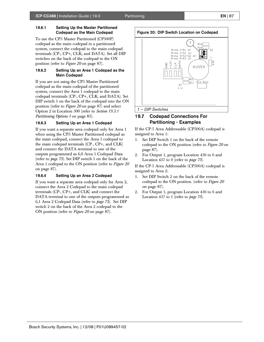
Figure 20: DIP Switch Location on Codepad

1

1 – DIP Switches

19.7Codepad Connections For Partitioning - Examples

If the CP-5 Area Addressable (CP500A) codepad is assigned to Area 1:

1.Set DIP Switch 1 on the back of the remote codepad to the ON position (refer to Figure 20 on page 87).

2.For Output 1, program Location 436 to 6 and Location 437 to 0 (refer to page 75).

If the CP-5 Area Addressable (CP500A) codepad is assigned to Area 2:

1.Set DIP Switch 2 on the back of the remote codepad to the ON position. (refer to Figure 20 on page 87).

2.For Output 1, program Location 436 to 6 and Location 437 to 1 (refer to page 75).

Bosch Security Systems, Inc. 12/08 F01U089457-02

Page 87
Image 87
Bosch Appliances ICP-CC488| Installation Guide, Partitioning, En, 19.6.3Setting Up an Area 1 Codepad, 1 – DIP Switches