Appendix D Technical Specifications
SFP and SFP+ Transceiver Specifications
Se n d d o c u m e n t a t i o n c o m m e n t s t o m d s f e e d b a ck - d o c @ c i s c o . c o m .
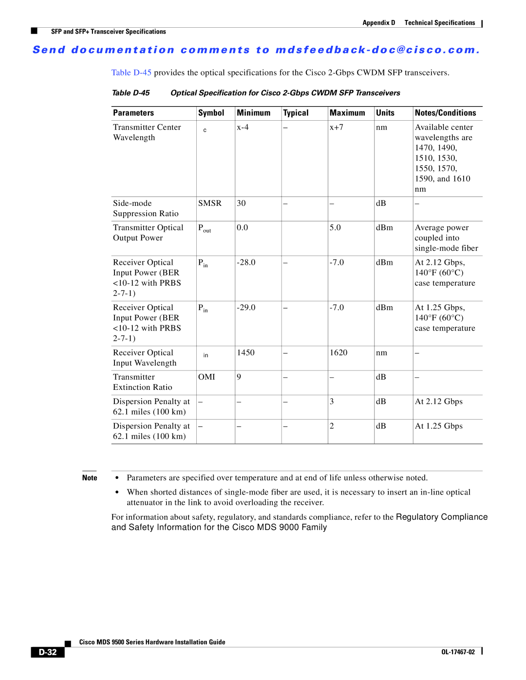
Table
|
| Table | Optical Specification for Cisco |
| |||||
|
|
|
|
|
|
|
|
|
|
|
| Parameters |
| Symbol | Minimum | Typical | Maximum | Units | Notes/Conditions |
|
|
|
|
|
|
|
|
| |
|
| Transmitter Center | λc | – | x+7 | nm | Available center | ||
|
| Wavelength |
|
|
|
|
|
| wavelengths are |
|
|
|
|
|
|
|
|
| 1470, 1490, |
|
|
|
|
|
|
|
|
| 1510, 1530, |
|
|
|
|
|
|
|
|
| 1550, 1570, |
|
|
|
|
|
|
|
|
| 1590, and 1610 |
|
|
|
|
|
|
|
|
| nm |
|
|
|
|
|
|
|
|
|
|
|
|
| SMSR | 30 | – | – | dB | – | |
|
| Suppression Ratio |
|
|
|
|
|
| |
|
|
|
|
|
|
|
|
| |
|
| Transmitter Optical | Pout | 0.0 |
| 5.0 | dBm | Average power | |
|
| Output Power |
|
|
|
|
|
| coupled into |
|
|
|
|
|
|
|
|
| |
|
|
|
|
|
|
|
|
| |
|
| Receiver Optical | Pin | – | dBm | At 2.12 Gbps, | |||
|
| Input Power (BER |
|
|
|
|
| 140°F (60°C) | |
|
|
|
|
|
|
| case temperature | ||
|
|
|
|
|
|
|
|
| |
|
|
|
|
|
|
|
|
| |
|
| Receiver Optical | Pin | – | dBm | At 1.25 Gbps, | |||
|
| Input Power (BER |
|
|
|
|
| 140°F (60°C) | |
|
|
|
|
|
|
| case temperature | ||
|
|
|
|
|
|
|
|
| |
|
|
|
|
|
|
|
|
| |
|
| Receiver Optical | λin | 1450 | – | 1620 | nm | – | |
|
| Input Wavelength |
|
|
|
|
|
| |
|
|
|
|
|
|
|
|
|
|
|
| Transmitter |
| OMI | 9 | – | – | dB | – |
|
| Extinction Ratio |
|
|
|
|
|
| |
|
|
|
|
|
|
|
|
| |
|
| Dispersion Penalty at | – | – | – | 3 | dB | At 2.12 Gbps | |
|
| 62.1 miles (100 km) |
|
|
|
|
|
| |
|
|
|
|
|
|
|
|
| |
|
| Dispersion Penalty at | – | – | – | 2 | dB | At 1.25 Gbps | |
|
| 62.1 miles (100 km) |
|
|
|
|
|
| |
|
|
|
|
|
|
|
| ||
|
|
|
|
|
|
|
|
|
|
Note | • Parameters are specified over temperature and at end of life unless otherwise noted. | ||||||||
•When shorted distances of
For information about safety, regulatory, and standards compliance, refer to the Regulatory Compliance and Safety Information for the Cisco MDS 9000 Family.
| Cisco MDS 9500 Series Hardware Installation Guide |
