Chapter 2 Installing the Cisco MDS 9500 Series
Removing and Installing a Power Supply or PEM
Se n d d o c u m e n t a t i o n c o m m e n t s t o m d s f e e d b a ck - d o c @ c i s c o . c o m .
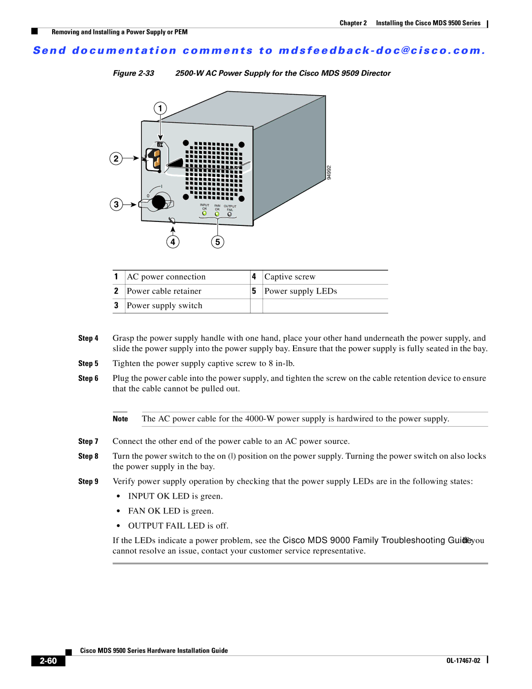
Figure 2-33 2500-W AC Power Supply for the Cisco MDS 9509 Director
1
2
![]() I
I
0
3
4
94992
INPUT | FAN | OUTPUT |
OK | OK | FAIL |
5
1 | AC power connection | 4 | Captive screw |
|
|
|
|
2 | Power cable retainer | 5 | Power supply LEDs |
|
|
|
|
3 | Power supply switch |
|
|
|
|
|
|
Step 4 Grasp the power supply handle with one hand, place your other hand underneath the power supply, and slide the power supply into the power supply bay. Ensure that the power supply is fully seated in the bay.
Step 5 Tighten the power supply captive screw to 8
Step 6 Plug the power cable into the power supply, and tighten the screw on the cable retention device to ensure that the cable cannot be pulled out.
Note The AC power cable for the
Step 7 Connect the other end of the power cable to an AC power source.
Step 8 Turn the power switch to the on () position on the power supply. Turning the power switch on also locks the power supply in the bay.
Step 9 Verify power supply operation by checking that the power supply LEDs are in the following states:
•INPUT OK LED is green.
•FAN OK LED is green.
•OUTPUT FAIL LED is off.
If the LEDs indicate a power problem, see the Cisco MDS 9000 Family Troubleshooting Guide. If you cannot resolve an issue, contact your customer service representative.
| Cisco MDS 9500 Series Hardware Installation Guide |