Chapter 2 Installing the Cisco MDS 9500 Series
Grounding the Chassis
Se n d d o c u m e n t a t i o n c o m m e n t s t o m d s f e e d b a ck - d o c @ c i s c o . c o m .
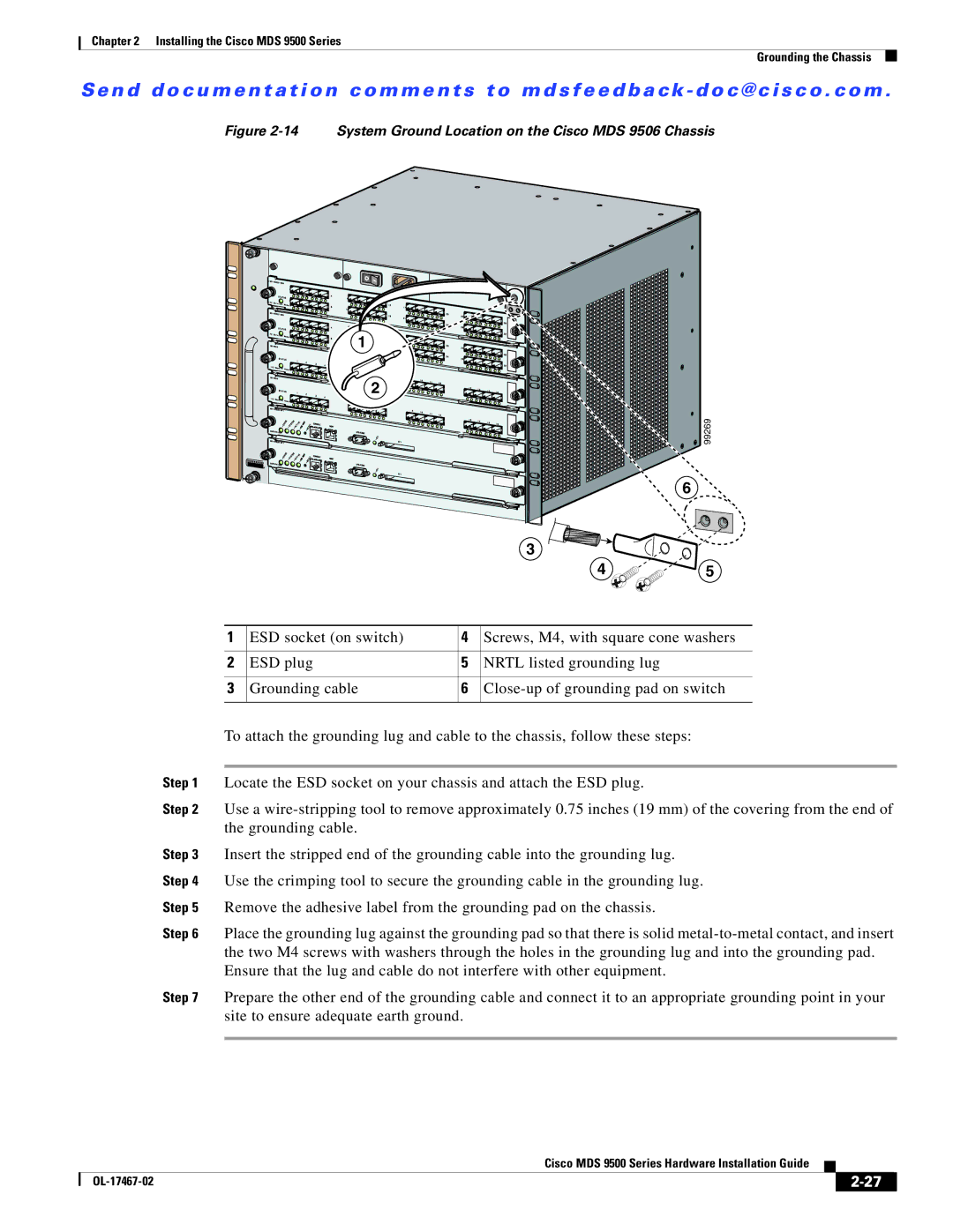
Figure 2-14 System Ground Location on the Cisco MDS 9506 Chassis
![]()
![]()
![]()
![]()
![]()
![]() 1
1![]()
![]()
![]()
![]()
![]()
![]()
![]()
![]()
![]()
![]()
![]()
![]()
![]()
![]()
![]()
![]()
![]() 2
2![]()
![]()
![]()
99269
6
|
|
| 3 |
|
|
|
| 4 | 5 |
1 | ESD socket (on switch) | 4 | Screws, M4, with square cone washers | |
2 | ESD plug | 5 | NRTL listed grounding lug |
|
3 | Grounding cable | 6 | ||
To attach the grounding lug and cable to the chassis, follow these steps:
Step 1 Locate the ESD socket on your chassis and attach the ESD plug.
Step 2 Use a
Step 3 Insert the stripped end of the grounding cable into the grounding lug.
Step 4 Use the crimping tool to secure the grounding cable in the grounding lug.
Step 5 Remove the adhesive label from the grounding pad on the chassis.
Step 6 Place the grounding lug against the grounding pad so that there is solid
Step 7 Prepare the other end of the grounding cable and connect it to an appropriate grounding point in your site to ensure adequate earth ground.
|
| Cisco MDS 9500 Series Hardware Installation Guide |
|
| |
|
|
| |||
|
|
|
| ||
|
|
|
| ||