Cisco Systems MDS 9500 Series manual Crossbar Modules, Crossbar Module LEDs

Models: MDS 9500 Series

1 288
Download 288 pages 59.22 Kb
Page 47
Image 47

Chapter 1 Product Overview

Crossbar Modules

Se n d d o c u m e n t a t i o n c o m m e n t s t o m d s f e e d b a ck - d o c @ c i s c o . c o m .

Crossbar Modules

The Cisco MDS 9513 Director supports two external crossbar modules located at the rear of the chassis. Each Supervisor-2 module has an associated external crossbar module for redundancy. The Supervisor-2 module in slot 7 is associated with crossbar module 1 and Supervisor-2 in slot 8 is associated with crossbar module 2. Redundant crossbar modules act in an active-active method, where each switching module forwards traffic across both crossbar fabrics based on the intended destination. The traffic load is shared across both crossbar modules. Each crossbar fabric channel connects to a fabric interface ASIC on the switching modules through serial links on the midplane. Each Supervisor-2 processor also has a 20-Gbps (40-Gbps FDX) link to each crossbar fabric for participating in management and control protocols and for in-band diagnostics.

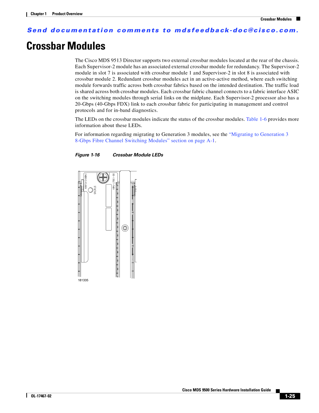
The LEDs on the crossbar modules indicate the status of the crossbar modules. Table 1-6provides more information about these LEDs.

For information regarding migrating to Generation 3 modules, see the “Migrating to Generation 3 8-Gbps Fibre Channel Switching Modules” section on page A-1.

Figure 1-16 Crossbar Module LEDs

181335


Cisco MDS 9500 Series Hardware Installation Guide


OL-17467-02


1-25


Page 47
Image 47
Cisco Systems MDS 9500 Series manual Crossbar Modules, Crossbar Module LEDs