Chapter 2 Installing the Cisco MDS 9500 Series
Removing and Installing Clock Modules
Se n d d o c u m e n t a t i o n c o m m e n t s t o m d s f e e d b a ck - d o c @ c i s c o . c o m .
•OUTPUT FAIL LED is off.
Removing a Clock Module from the Cisco MDS 9509 Director
Before installing the clock module, check the contents of your kit. Table
Table | Contents of Cisco MDS 9509 Clock Module Replacement Kits | |
|
|
|
Quantity | Part Description | |
|
|
|
1 | Cisco MDS 9509 clock module | |
|
|
|
12 | M3 x | |
|
|
|
1 | Disposable ESD wrist strap | |
|
|
|
These tools are required to remove or install a clock module:
•Number 1 Phillips screwdriver
•Your own
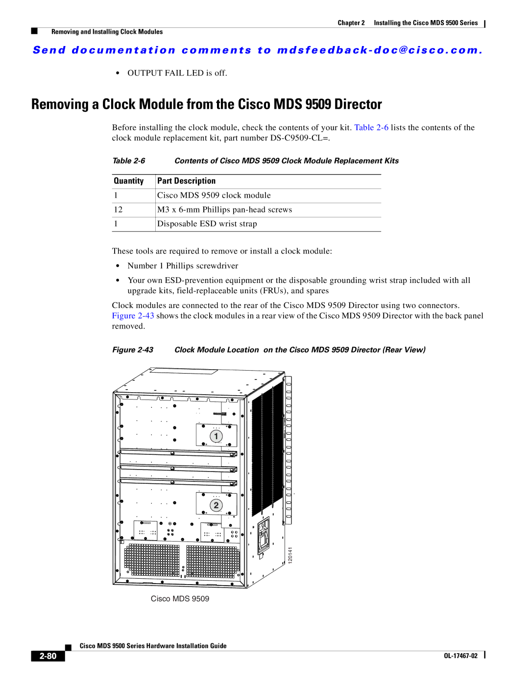
Clock modules are connected to the rear of the Cisco MDS 9509 Director using two connectors. Figure
Figure 2-43 Clock Module Location on the Cisco MDS 9509 Director (Rear View)
1
2
120141
Cisco MDS 9509
| Cisco MDS 9500 Series Hardware Installation Guide |