Chapter 1 Product Overview
Chassis
Se n d d o c u m e n t a t i o n c o m m e n t s t o m d s f e e d b a ck - d o c @ c i s c o . c o m .
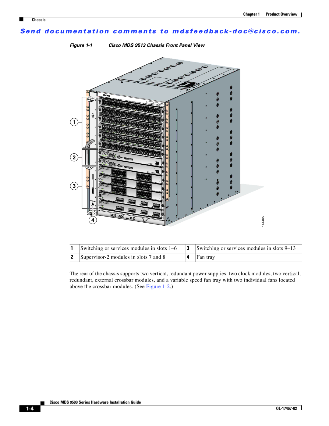
Figure 1-1 Cisco MDS 9513 Chassis Front Panel View
1 |
|
| |
2 |
|
| |
3 |
|
| |
| 4 |
| 144465 |
|
|
| |
1 | Switching or services modules in slots | 3 | Switching or services modules in slots |
2 | 4 | Fan tray | |
The rear of the chassis supports two vertical, redundant power supplies, two clock modules, two vertical, redundant, external crossbar modules, and a variable speed fan tray with two individual fans located above the crossbar modules. (See Figure
Cisco MDS 9500 Series Hardware Installation Guide
| ||
|
