CY7C67300
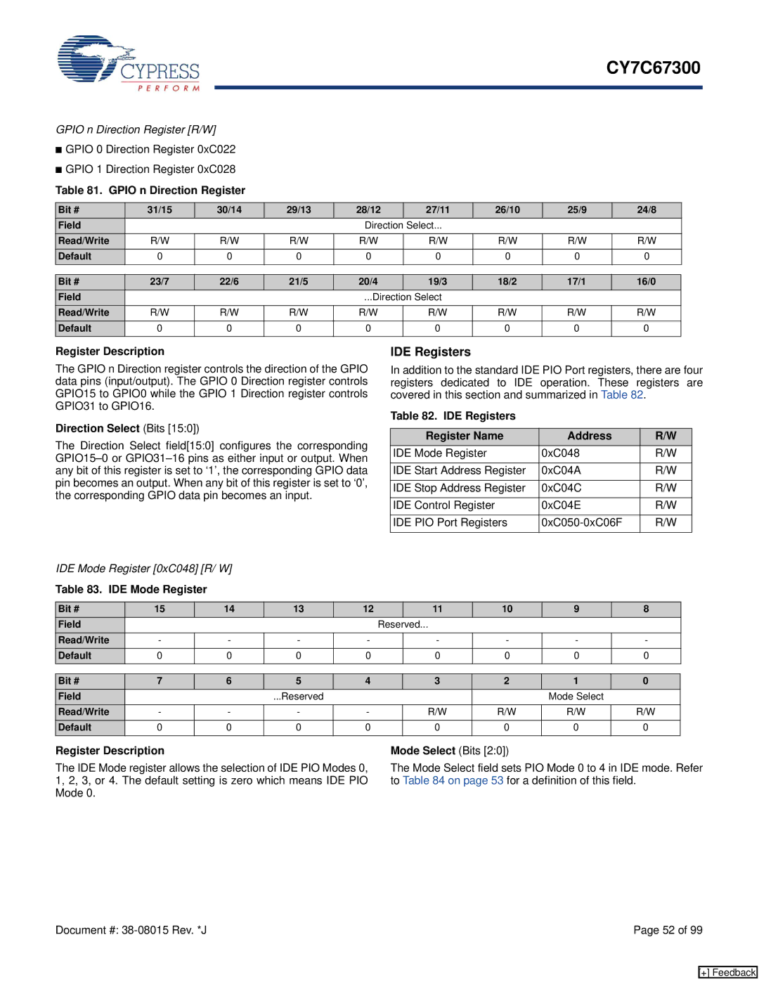
GPIO n Direction Register [R/W]
■GPIO 0 Direction Register 0xC022
■GPIO 1 Direction Register 0xC028
Table 81. GPIO n Direction Register
Bit # | 31/15 | 30/14 | 29/13 | 28/12 | 27/11 | 26/10 | 25/9 | 24/8 |
Field |
|
|
| Direction Select... |
|
|
| |
Read/Write | R/W | R/W | R/W | R/W | R/W | R/W | R/W | R/W |
Default | 0 | 0 | 0 | 0 | 0 | 0 | 0 | 0 |
Bit # | 23/7 | 22/6 | 21/5 | 20/4 | 19/3 | 18/2 | 17/1 | 16/0 |
Field |
|
|
| ...Direction Select |
|
|
| |
Read/Write | R/W | R/W | R/W | R/W | R/W | R/W | R/W | R/W |
Default | 0 | 0 | 0 | 0 | 0 | 0 | 0 | 0 |
Register Description
The GPIO n Direction register controls the direction of the GPIO data pins (input/output). The GPIO 0 Direction register controls GPIO15 to GPIO0 while the GPIO 1 Direction register controls GPIO31 to GPIO16.
Direction Select (Bits [15:0])
The Direction Select field[15:0] configures the corresponding
IDE Mode Register [0xC048] [R/ W]
Table 83. IDE Mode Register
IDE Registers
In addition to the standard IDE PIO Port registers, there are four registers dedicated to IDE operation. These registers are covered in this section and summarized in Table 82.
Table 82. IDE Registers
Register Name | Address | R/W |
IDE Mode Register | 0xC048 | R/W |
|
|
|
IDE Start Address Register | 0xC04A | R/W |
|
|
|
IDE Stop Address Register | 0xC04C | R/W |
|
|
|
IDE Control Register | 0xC04E | R/W |
|
|
|
IDE PIO Port Registers | R/W | |
|
|
|
Bit # | 15 | 14 | 13 | 12 |
| 11 | 10 | 9 | 8 |
Field |
|
|
|
| Reserved... |
|
|
| |
Read/Write | - | - | - | - |
| - | - | - | - |
Default | 0 | 0 | 0 | 0 |
| 0 | 0 | 0 | 0 |
Bit # | 7 | 6 | 5 | 4 | 3 | 2 | 1 | 0 |
Field |
|
| ...Reserved |
|
|
| Mode Select |
|
Read/Write | - | - | - | - | R/W | R/W | R/W | R/W |
Default | 0 | 0 | 0 | 0 | 0 | 0 | 0 | 0 |
Register Description
The IDE Mode register allows the selection of IDE PIO Modes 0, 1, 2, 3, or 4. The default setting is zero which means IDE PIO Mode 0.
Mode Select (Bits [2:0])
The Mode Select field sets PIO Mode 0 to 4 in IDE mode. Refer to Table 84 on page 53 for a definition of this field.
Document #: | Page 52 of 99 |
[+] Feedback