CY7C67300
Mode Select (Bit 8)
The Mode Select bit selects between continuous PWM cycling and one shot mode. The default is continuous repeat.
1:Enable One Shot mode. The mode runs the number of counter cycles set in the PWM Cycle Count register and then stops.
0:Enable Continuous mode. Runs in continuous mode and starts over after the PWM cycle count is reached.
PWM 3 Polarity Select (Bit 7)
The PWM 3 Polarity Select bit selects the polarity for PWM 3.
1:Sets the polarity to active HIGH or rising edge pulse
0:Sets the polarity to active LOW
PWM 2 Polarity Select (Bit 6)
The PWM 2 Polarity Select bit selects the polarity for PWM 2.
1:Sets the polarity to active HIGH or rising edge pulse
0:Sets the polarity to active LOW
PWM 1 Polarity Select (Bit 5)
The PWM 1 Polarity Select bit selects the polarity for PWM 1.
1:Sets the polarity to active HIGH or rising edge pulse
0:Sets the polarity to active LOW
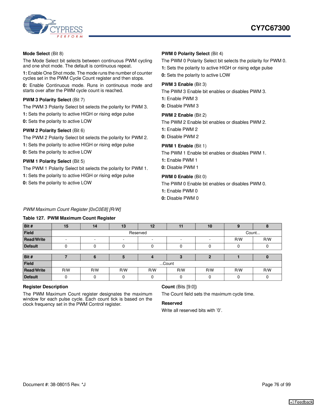
PWM Maximum Count Register [0xC0E8] [R/W]
Table 127. PWM Maximum Count Register
PWM 0 Polarity Select (Bit 4)
The PWM 0 Polarity Select bit selects the polarity for PWM 0.
1:Sets the polarity to active HIGH or rising edge pulse
0:Sets the polarity to active LOW
PWM 3 Enable (Bit 3)
The PWM 3 Enable bit enables or disables PWM 3.
1:Enable PWM 3
0:Disable PWM 3
PWM 2 Enable (Bit 2)
The PWM 2 Enable bit enables or disables PWM 2.
1:Enable PWM 2
0:Disable PWM 2
PWM 1 Enable (Bit 1)
The PWM 1 Enable bit enables or disables PWM 1.
1:Enable PWM 1
0:Disable PWM 1
PWM 0 Enable (Bit 0)
The PWM 0 Enable bit enables or disables PWM 0.
1:Enable PWM 0
0:Disable PWM 0
Bit # | 15 | 14 | 13 |
| 12 | 11 | 10 | 9 |
| 8 |
Field |
|
|
| Reserved |
|
|
| Count... | ||
Read/Write | - | - | - |
| - | - | - | R/W |
| R/W |
Default | 0 | 0 | 0 |
| 0 | 0 | 0 | 0 |
| 0 |
|
|
|
|
|
|
|
|
|
|
|
Bit # | 7 | 6 | 5 | 4 |
| 3 | 2 | 1 | 0 |
Field |
|
|
|
| ...Count |
|
|
| |
Read/Write | R/W | R/W | R/W | R/W |
| R/W | R/W | R/W | R/W |
Default | 0 | 0 | 0 | 0 |
| 0 | 0 | 0 | 0 |
|
|
|
|
|
|
|
|
|
|
Register Description
The PWM Maximum Count register designates the maximum window for each pulse cycle. Each count tick is based on the clock frequency set in the PWM Control register.
Count (Bits [9:0])
The Count field sets the maximum cycle time.
Reserved
Write all reserved bits with ’0’.
Document #: | Page 76 of 99 |
[+] Feedback