|
|
|
|
|
|
|
|
|
|
|
| CY7C67300 | ||||
|
|
|
|
|
|
|
|
|
|
|
|
|
|
|
|
|
|
|
|
|
|
|
|
|
|
|
|
|
|
|
|
| |
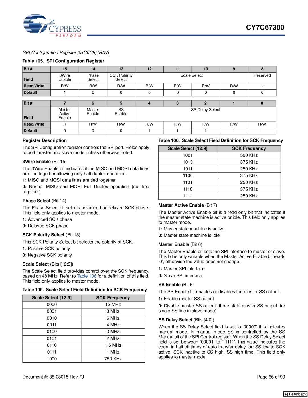
SPI Configuration Register [0xC0C8] [R/W] |
|
|
|
|
|
|
|
|
|
|
| |||||
Table 105. SPI Configuration Register |
|
|
|
|
|
|
|
|
|
|
| |||||
|
|
|
|
|
|
|
|
|
|
|
|
|
|
| ||
Bit # | 15 | 14 |
| 13 | 12 | 11 | 10 |
| 9 |
| 8 |
|
|
| ||
Field | 3Wire |
|
| Phase |
| SCK Polarity |
| Scale Select |
|
| Reserved |
| ||||
Enable |
|
| Select |
| Select |
|
|
|
|
|
|
|
|
|
| |
Read/Write | R/W |
|
| R/W |
| R/W | R/W | R/W | R/W |
| R/W |
| - |
|
|
|
Default | 1 | 0 |
| 0 | 0 | 0 | 0 |
| 0 |
| 0 |
|
|
| ||
|
|
|
|
|
|
|
|
|
|
|
|
|
|
|
|
|
Bit # | 7 | 6 |
| 5 | 4 | 3 | 2 |
| 1 |
| 0 |
|
|
| ||
| Master | Master |
| SS |
|
| SS Delay Select |
|
|
|
|
|
| |||
Field | Active | Enable |
| Enable |
|
|
|
|
|
|
|
|
|
| ||
Enable |
|
|
|
|
|
|
|
|
|
|
|
|
|
|
| |
Read/Write | R |
|
| R/W |
| R/W | R/W | R/W | R/W |
| R/W |
| R/W |
|
|
|
Default | 0 | 0 |
| 0 | 1 | 1 | 1 |
| 1 |
| 1 |
|
|
| ||
|
|
|
|
|
|
|
|
|
|
|
|
|
|
|
|
|
Register Description
The SPI Configuration register controls the SPI port. Fields apply to both master and slave mode unless otherwise noted.
3Wire Enable (Bit 15)
The 3Wire Enable bit indicates if the MISO and MOSI data lines are tied together allowing only half duplex operation.
1:MISO and MOSI data lines are tied together
0:Normal MISO and MOSI Full Duplex operation (not tied together)
Phase Select (Bit 14)
The Phase Select bit selects advanced or delayed SCK phase. This field only applies to master mode.
1:Advanced SCK phase
0:Delayed SCK phase
SCK Polarity Select (Bit 13)
This SCK Polarity Select bit selects the polarity of SCK.
1:Positive SCK polarity
0:Negative SCK polarity
Scale Select (Bits [12:9])
The Scale Select field provides control over the SCK frequency, based on 48 MHz. Refer to Table 106 for a definition of this field. This field only applies to master mode.
Table 106. Scale Select Field Definition for SCK Frequency
Scale Select [12:9] | SCK Frequency |
0000 | 12 MHz |
|
|
0001 | 8 MHz |
|
|
0010 | 6 MHz |
|
|
0011 | 4 MHz |
|
|
0100 | 3 MHz |
|
|
0101 | 2 MHz |
|
|
0110 | 1.5 MHz |
|
|
0111 | 1 MHz |
|
|
1000 | 750 KHz |
|
|
Table 106. Scale Select Field Definition for SCK Frequency
Scale Select [12:9] | SCK Frequency |
1001 | 500 KHz |
|
|
1010 | 375 KHz |
|
|
1011 | 250 KHz |
|
|
1100 | 375 KHz |
|
|
1101 | 250 KHz |
|
|
1110 | 375 KHz |
|
|
1111 | 250 KHz |
|
|
Master Active Enable (Bit 7)
The Master Active Enable bit is a read only bit that indicates if the master state machine is active or idle. This field only applies to master mode.
1:Master state machine is active
0:Master state machine is idle
Master Enable (Bit 6)
The Master Enable bit sets the SPI interface to master or slave. This bit is only writable when the Master Active Enable bit reads ‘0’, otherwise the value does not change.
1:Master SPI interface
0:Slave SPI interface
SS Enable (Bit 5)
The SS Enable bit enables or disables the master SS output.
1:Enable master SS output
0:Disable master SS output (three state master SS output, for single SS line in slave mode)
SS Delay Select (Bits [4:0])
When the SS Delay Select field is set to ‘00000’ this indicates manual mode. In manual mode SS is controlled by the SS Manual bit of the SPI Control register. When the SS Delay Select field is set between ‘00001’ to ‘11111’, this value indicates the count in half bit times of auto transfer delay for: SS low to SCK active, SCK inactive to SS high, SS high time. This field only applies to master mode.
Document #: | Page 66 of 99 |
[+] Feedback