CY7C67300
The Device n Endpoint n Count Result register is a
Result (Bits [15:0])
The Result field contains the differences in bytes between the received packet and the value specified in the Device n Endpoint n Count register. If an overflow condition occurs, Result [15:10] is set to ‘111111’, a 2’s complement value indicating the
Device n Port Select Register [R/W]
■Device n Port Select Register 0xC084
■Device n Port Select Register 0xC0A4
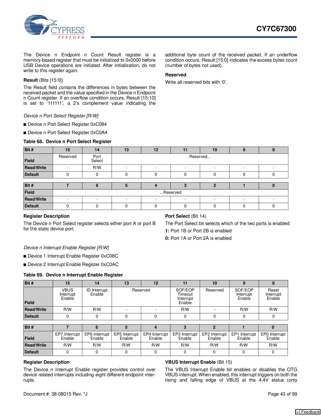
Table 68. Device n Port Select Register
additional byte count of the received packet. If an underflow condition occurs, Result [15:0] indicates the excess bytes count (number of bytes not used).
Reserved
Write all reserved bits with ‘0’.
Bit # | 15 | 14 | 13 | 12 | 11 |
| 10 | 9 | 8 |
Field | Reserved | Port |
|
|
| Reserved... |
|
| |
| Select |
|
|
|
|
|
|
| |
Read/Write | - | R/W | - | - | - |
| - | - | - |
Default | 0 | 0 | 0 | 0 | 0 |
| 0 | 0 | 0 |
|
|
|
|
|
|
|
|
|
|
Bit # | 7 | 6 | 5 | 4 |
| 3 | 2 | 1 | 0 |
Field |
|
|
|
| ...Reserved |
|
|
| |
Read/Write | - | - | - | - |
| - | - | - | - |
Default | 0 | 0 | 0 | 0 |
| 0 | 0 | 0 | 0 |
|
|
|
|
|
|
|
|
|
|
Register Description
The Device n Port Select register selects either port A or port B for the static device port.
Device n Interrupt Enable Register [R/W]
■Device 1 Interrupt Enable Register 0xC08C
■Device 2 Interrupt Enable Register 0xC0AC
Table 69. Device n Interrupt Enable Register
Port Select (Bit 14)
The Port Select bit selects which of the two ports is enabled.
1:Port 1B or Port 2B is enabled
0:Port 1A or Port 2A is enabled
Bit # | 15 | 14 | 13 |
| 12 | 11 | 10 | 9 | 8 |
| VBUS | ID Interrupt | Reserved |
| SOF/EOP | Reserved | SOF/EOP | Reset | |
| Interrupt | Enable |
|
|
| Timeout |
| Interrupt | Interrupt |
Field | Enable |
|
|
|
| Interrupt |
| Enable | Enable |
|
|
|
|
| Enable |
|
|
| |
Read/Write | R/W | R/W | - |
| - | R/W | - | R/W | R/W |
Default | 0 | 0 | 0 |
| 0 | 0 | 0 | 0 | 0 |
|
|
|
|
|
|
|
|
|
|
Bit # | 7 | 6 | 5 | 4 | 3 | 2 | 1 | 0 |
Field | EP7 Interrupt | EP6 Interrupt | EP5 Interrupt | EP4 Interrupt | EP3 Interrupt | EP2 Interrupt | EP1 Interrupt | EP0 Interrupt |
Enable | Enable | Enable | Enable | Enable | Enable | Enable | Enable | |
Read/Write | R/W | R/W | R/W | R/W | R/W | R/W | R/W | R/W |
Default | 0 | 0 | 0 | 0 | 0 | 0 | 0 | 0 |
|
|
|
|
|
|
|
|
|
Register Description
The Device n Interrupt Enable register provides control over device related interrupts including eight different endpoint inter- rupts.
VBUS Interrupt Enable (Bit 15)
The VBUS Interrupt Enable bit enables or disables the OTG VBUS interrupt. When enabled, this interrupt triggers on both the rising and falling edge of VBUS at the 4.4V status (only
Document #: | Page 43 of 99 |
[+] Feedback