CY7C67300
Introduction
Interrupts
General Timers and Watchdog Timer
Functional Overview
An overview of the processor core components are presented in this section.
Processor Core
Clocking
Memory
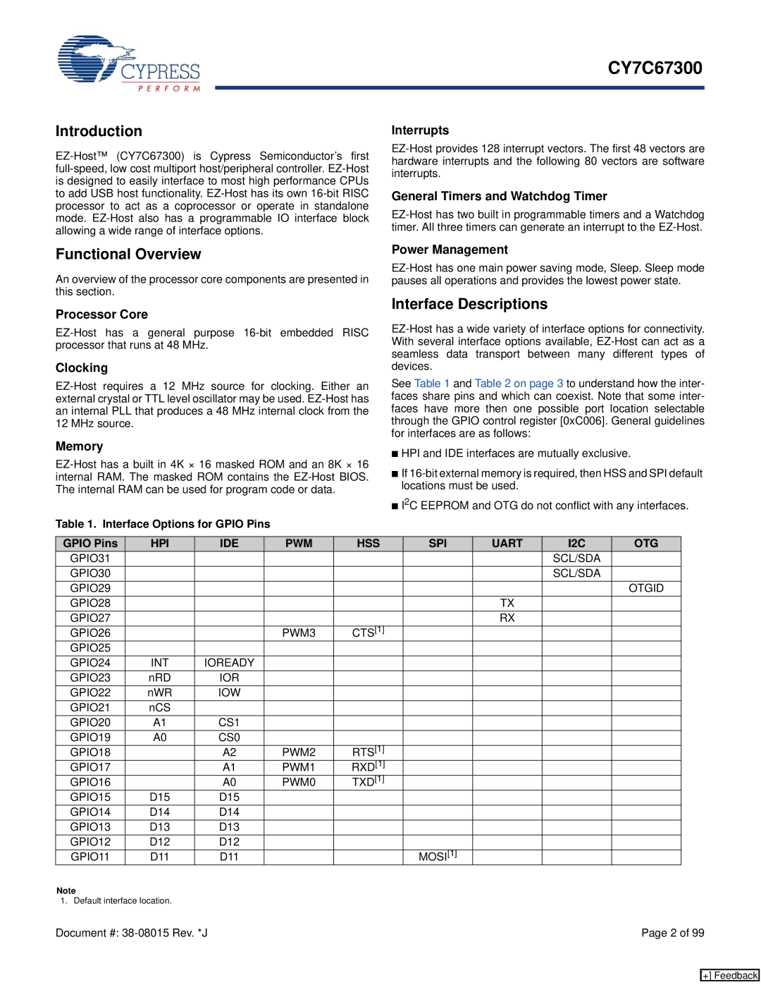
Table 1. Interface Options for GPIO Pins
Power Management
Interface Descriptions
See Table 1 and Table 2 on page 3 to understand how the inter- faces share pins and which can coexist. Note that some inter- faces have more then one possible port location selectable through the GPIO control register [0xC006]. General guidelines for interfaces are as follows:
■HPI and IDE interfaces are mutually exclusive.
■If
■I2C EEPROM and OTG do not conflict with any interfaces.
GPIO Pins | HPI | IDE | PWM | HSS | SPI | UART | I2C | OTG |
GPIO31 |
|
|
|
|
|
| SCL/SDA |
|
GPIO30 |
|
|
|
|
|
| SCL/SDA |
|
GPIO29 |
|
|
|
|
|
|
| OTGID |
GPIO28 |
|
|
|
|
| TX |
|
|
GPIO27 |
|
|
|
|
| RX |
|
|
GPIO26 |
|
| PWM3 | CTS[1] |
|
|
|
|
GPIO25 |
|
|
|
|
|
|
|
|
GPIO24 | INT | IOREADY |
|
|
|
|
|
|
GPIO23 | nRD | IOR |
|
|
|
|
|
|
GPIO22 | nWR | IOW |
|
|
|
|
|
|
GPIO21 | nCS |
|
|
|
|
|
|
|
GPIO20 | A1 | CS1 |
|
|
|
|
|
|
GPIO19 | A0 | CS0 |
|
|
|
|
|
|
GPIO18 |
| A2 | PWM2 | RTS[1] |
|
|
|
|
GPIO17 |
| A1 | PWM1 | RXD[1] |
|
|
|
|
GPIO16 |
| A0 | PWM0 | TXD[1] |
|
|
|
|
GPIO15 | D15 | D15 |
|
|
|
|
|
|
GPIO14 | D14 | D14 |
|
|
|
|
|
|
GPIO13 | D13 | D13 |
|
|
|
|
|
|
GPIO12 | D12 | D12 |
|
|
|
|
|
|
GPIO11 | D11 | D11 |
|
| MOSI[1] |
|
|
|
Note
1. Default interface location. |
|
Document #: | Page 2 of 99 |
[+] Feedback