CY7C67300
Receive Interrupt Flag (Bit 2)
The Receive Interrupt Flag is a read only bit that indicates if a byte mode receive interrupt triggered.
1:Indicates a byte mode receive interrupt triggered
0:Indicates a byte mode receive interrupt did not trigger
Transmit Interrupt Flag (Bit 1)
The Transmit Interrupt Flag is a read only bit that indicates a byte mode transmit interrupt triggered.
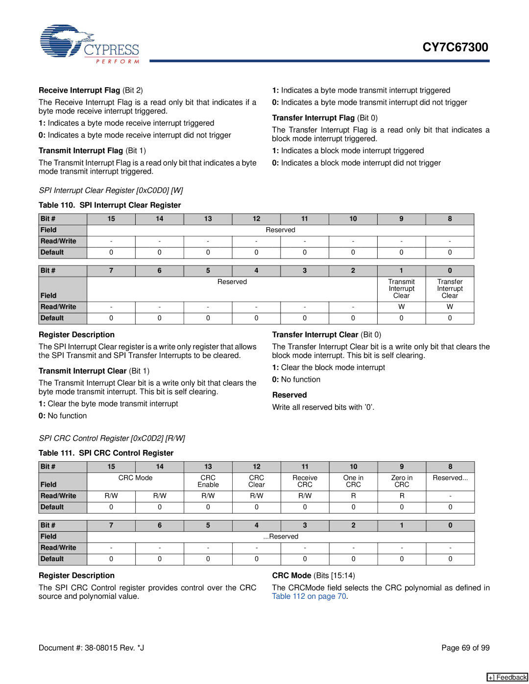
SPI Interrupt Clear Register [0xC0D0] [W]
Table 110. SPI Interrupt Clear Register
1:Indicates a byte mode transmit interrupt triggered
0:Indicates a byte mode transmit interrupt did not trigger
Transfer Interrupt Flag (Bit 0)
The Transfer Interrupt Flag is a read only bit that indicates a block mode interrupt triggered.
1:Indicates a block mode interrupt triggered
0:Indicates a block mode interrupt did not trigger
Bit # | 15 | 14 | 13 | 12 |
| 11 | 10 | 9 | 8 |
Field |
|
|
|
| Reserved |
|
|
| |
Read/Write | - | - | - | - |
| - | - | - | - |
Default | 0 | 0 | 0 | 0 |
| 0 | 0 | 0 | 0 |
|
|
|
|
|
|
|
|
|
|
Bit # | 7 | 6 | 5 |
| 4 | 3 | 2 | 1 | 0 |
|
|
|
| Reserved |
|
| Transmit | Transfer | |
Field |
|
|
|
|
|
|
| Interrupt | Interrupt |
|
|
|
|
|
|
| Clear | Clear | |
Read/Write | - | - | - |
| - | - | - | W | W |
Default | 0 | 0 | 0 |
| 0 | 0 | 0 | 0 | 0 |
|
|
|
|
|
|
|
|
|
|
Register Description
The SPI Interrupt Clear register is a write only register that allows the SPI Transmit and SPI Transfer Interrupts to be cleared.
Transmit Interrupt Clear (Bit 1)
The Transmit Interrupt Clear bit is a write only bit that clears the byte mode transmit interrupt. This bit is self clearing.
1:Clear the byte mode transmit interrupt
0:No function
SPI CRC Control Register [0xC0D2] [R/W]
Table 111. SPI CRC Control Register
Transfer Interrupt Clear (Bit 0)
The Transfer Interrupt Clear bit is a write only bit that clears the block mode interrupt. This bit is self clearing.
1:Clear the block mode interrupt
0:No function
Reserved
Write all reserved bits with ’0’.
Bit # | 15 |
| 14 | 13 | 12 | 11 | 10 | 9 | 8 |
Field | CRC Mode |
| CRC | CRC | Receive | One in | Zero in | Reserved... | |
|
|
| Enable | Clear | CRC | CRC | CRC |
| |
Read/Write | R/W |
| R/W | R/W | R/W | R/W | R | R | - |
Default | 0 |
| 0 | 0 | 0 | 0 | 0 | 0 | 0 |
|
|
|
|
|
|
|
|
|
|
Bit # | 7 | 6 | 5 | 4 |
| 3 | 2 | 1 | 0 |
Field |
|
|
|
| ...Reserved |
|
|
| |
Read/Write | - | - | - | - |
| - | - | - | - |
Default | 0 | 0 | 0 | 0 |
| 0 | 0 | 0 | 0 |
|
|
|
|
|
|
|
|
|
|
Register Description
The SPI CRC Control register provides control over the CRC source and polynomial value.
CRC Mode (Bits [15:14)
The CRCMode field selects the CRC polynomial as defined in Table 112 on page 70.
Document #: | Page 69 of 99 |
[+] Feedback