CY7C67300
External Memory Interface Pins
Table 6. External Memory Interface Pins
Pin Name | Pin Number |
nWR | 64 |
|
|
nRD | 62 |
|
|
nXMEMSEL (optional nCS) | 34 |
|
|
nXROMSEL (ROM nCS) | 35 |
|
|
nXRAMSEL (RAM nCS) | 36 |
|
|
A18 | 95 |
|
|
A17 | 96 |
|
|
A16 | 97 |
|
|
A15 | 38 |
|
|
A14 | 33 |
|
|
A13 | 32 |
|
|
A12 | 31 |
|
|
A11 | 30 |
|
|
A10 | 27 |
|
|
A9 | 25 |
|
|
A8 | 24 |
|
|
A7 | 20 |
|
|
A6 | 17 |
|
|
A5 | 8 |
|
|
A4 | 7 |
|
|
A3 | 3 |
|
|
A2 | 2 |
|
|
A1 | 1 |
|
|
nBEL/A0 | 99 |
|
|
nBEH | 98 |
|
|
D15 | 67 |
|
|
D14 | 68 |
|
|
D13 | 69 |
|
|
D12 | 70 |
|
|
D11 | 71 |
|
|
D10 | 72 |
|
|
D9 | 73 |
|
|
D8 | 74 |
|
|
D7 | 76 |
|
|
D6 | 77 |
|
|
D5 | 78 |
|
|
D4 | 79 |
|
|
Table 6. External Memory Interface Pins (continued)
Pin Name | Pin Number |
D3 | 80 |
|
|
D2 | 81 |
|
|
D1 | 82 |
|
|
D0 | 83 |
|
|
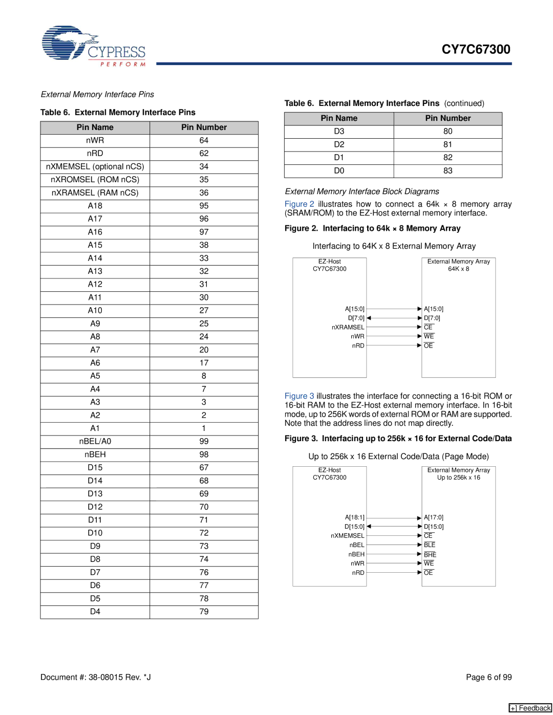
External Memory Interface Block Diagrams
Figure 2 illustrates how to connect a 64k × 8 memory array (SRAM/ROM) to the EZ-Host external memory interface.
Figure 2. Interfacing to 64k × 8 Memory Array
Interfacing to 64K x 8 External Memory Array
| External Memory Array | |
CY7C67300 |
| 64K x 8 |
A[15:0] ![]() A[15:0]
A[15:0]
D[7:0] ![]()
![]() D[7:0]
D[7:0]
nXRAMSEL ![]() CE
CE
nWR ![]() WE
WE
nRD ![]() OE
OE
Figure 3 illustrates the interface for connecting a 16-bit ROM or 16-bit RAM to the EZ-Host external memory interface. In 16-bit mode, up to 256K words of external ROM or RAM are supported. Note that the address lines do not map directly.
Figure 3. Interfacing up to 256k × 16 for External Code/Data
Up to 256k x 16 External Code/Data (Page Mode)
| External Memory Array | |
CY7C67300 |
| Up to 256k x 16 |
A[18:1] ![]() A[17:0]
A[17:0]
D[15:0] ![]()
![]() D[15:0]
D[15:0]
nXMEMSEL ![]() CE
CE
nBEL ![]() BLE
BLE
nBEH ![]() BHE
BHE
nWR ![]() WE
WE
nRD ![]() OE
OE
Document #: | Page 6 of 99 |
[+] Feedback