CY7C67300
SOF/EOP Interrupt Flag (Bit 9)
The SOF/EOP Interrupt Flag bit indicates the status of the SOF/EOP Timer interrupt. This bit triggers ‘1’ when the SOF/EOP timer expires.
1:Interrupt triggered
0:Interrupt did not trigger
Port B Wake Interrupt Flag (Bit 7)
The Port B Wake Interrupt Flag bit indicates remote wakeup on PortB.
1:Interrupt triggered
0:Interrupt did not trigger
Port A Wake Interrupt Flag (Bit 6)
The Port A Wake Interrupt Flag bit indicates remote wakeup on PortA.
1:Interrupt triggered
0:Interrupt did not trigger
Port B Connect Change Interrupt Flag (Bit 5)
The Port B Connect Change Interrupt Flag bit indicates the status of the Connect Change interrupt on Port B. This bit triggers ‘1’ on either a rising edge or falling edge of a USB Reset condition (device inserted or removed). Together with the Port B SE0 Status bit, it can be determined whether a device was inserted or removed.
1:Interrupt triggered
0:Interrupt did not trigger
Port A Connect Change Interrupt Flag (Bit 4)
The Port A Connect Change Interrupt Flag bit indicates the status of the Connect Change interrupt on Port A. This bit
Host n SOF/EOP Count Register [R/W]
■Host 1 SOF/EOP Count Register 0xC092
■Host 2 SOF/EOP Count Register 0xC0B2
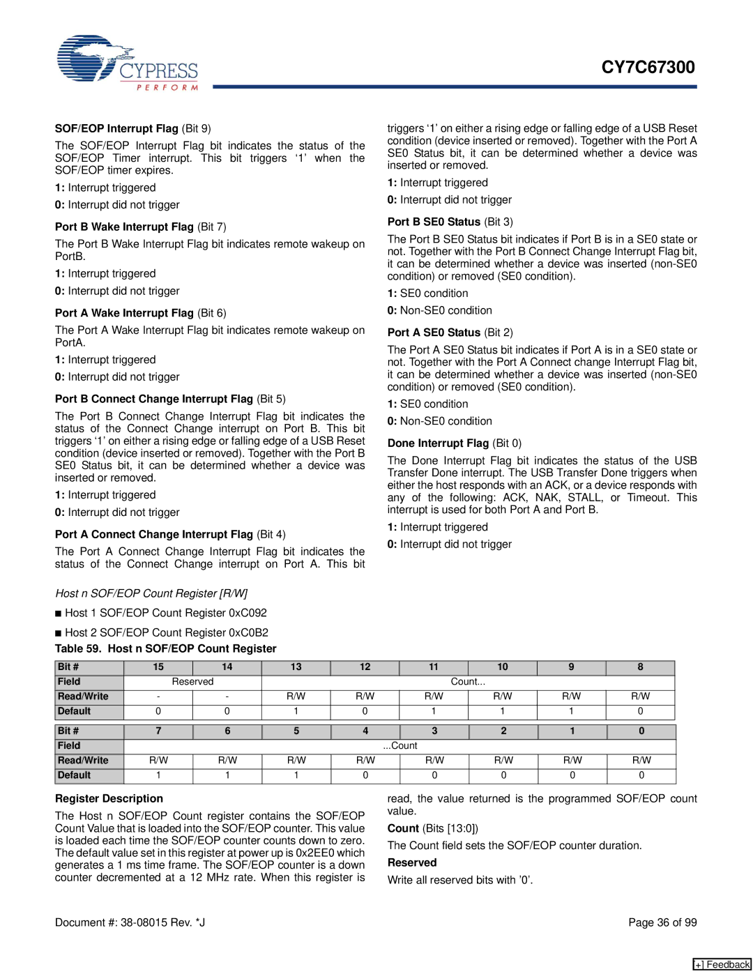
Table 59. Host n SOF/EOP Count Register
triggers ‘1’ on either a rising edge or falling edge of a USB Reset condition (device inserted or removed). Together with the Port A SE0 Status bit, it can be determined whether a device was inserted or removed.
1:Interrupt triggered
0:Interrupt did not trigger
Port B SE0 Status (Bit 3)
The Port B SE0 Status bit indicates if Port B is in a SE0 state or not. Together with the Port B Connect Change Interrupt Flag bit, it can be determined whether a device was inserted
1:SE0 condition
0:
Port A SE0 Status (Bit 2)
The Port A SE0 Status bit indicates if Port A is in a SE0 state or not. Together with the Port A Connect change Interrupt Flag bit, it can be determined whether a device was inserted
1:SE0 condition
0:
Done Interrupt Flag (Bit 0)
The Done Interrupt Flag bit indicates the status of the USB Transfer Done interrupt. The USB Transfer Done triggers when either the host responds with an ACK, or a device responds with any of the following: ACK, NAK, STALL, or Timeout. This interrupt is used for both Port A and Port B.
1:Interrupt triggered
0:Interrupt did not trigger
Bit # | 15 |
| 14 | 13 | 12 | 11 |
| 10 | 9 | 8 |
Field | Reserved |
|
|
|
| Count... |
|
| ||
Read/Write | - |
| - | R/W | R/W | R/W |
| R/W | R/W | R/W |
Default | 0 |
| 0 | 1 | 0 | 1 |
| 1 | 1 | 0 |
Bit # | 7 | 6 | 5 | 4 |
| 3 | 2 | 1 | 0 |
Field |
|
|
|
| ...Count |
|
|
| |
Read/Write | R/W | R/W | R/W | R/W |
| R/W | R/W | R/W | R/W |
Default | 1 | 1 | 1 | 0 |
| 0 | 0 | 0 | 0 |
Register Description
The Host n SOF/EOP Count register contains the SOF/EOP Count Value that is loaded into the SOF/EOP counter. This value is loaded each time the SOF/EOP counter counts down to zero. The default value set in this register at power up is 0x2EE0 which generates a 1 ms time frame. The SOF/EOP counter is a down counter decremented at a 12 MHz rate. When this register is
read, the value returned is the programmed SOF/EOP count value.
Count (Bits [13:0])
The Count field sets the SOF/EOP counter duration.
Reserved
Write all reserved bits with ’0’.
Document #: | Page 36 of 99 |
[+] Feedback