CY7C67300
Device n SOF/EOP Count Register [W]
■Device 1 SOF/EOP Count Register 0xC094
■Device 2 SOF/EOP Count Register 0xC0B4
Table 73. Device n SOF/EOP Count Register
Bit # | 15 |
| 14 | 13 | 12 | 11 |
| 10 | 9 | 8 |
Field | Reserved |
|
|
|
| Count... |
|
| ||
Read/Write | - |
| - | R | R | R |
| R | R | R |
Default | 0 |
| 0 | 1 | 0 | 1 |
| 1 | 1 | 0 |
|
|
|
|
|
|
|
|
|
|
|
Bit # | 7 | 6 | 5 | 4 |
| 3 | 2 | 1 | 0 |
Field |
|
|
|
| ...Count |
|
|
| |
Read/Write | R | R | R | R |
| R | R | R | R |
Default | 1 | 1 | 1 | 0 |
| 0 | 0 | 0 | 0 |
|
|
|
|
|
|
|
|
|
|
Register Description
The Device n SOF/EOP Count register is written with the time expected between receiving a SOF/EOP. If the SOF/EOP counter expires before an SOF/EOP is received, an SOF/EOP Timeout Interrupt can be generated. The SOF/EOP Timeout Interrupt Enable and SOF/EOP Timeout Interrupt Flag are located in the Device n Interrupt Enable and Status registers respectively.
Set the SOF/EOP count slightly greater than the expected SOF/EOP interval. The SOF/EOP counter decrements at a 12 MHz rate. Therefore, in the case of an expected 1 ms SOF/EOP interval, the SOF/EOP count is set slightly greater than 0x2EE0.
Count (Bits [13:0])
The Count field contains the current value of the SOF/EOP down counter. At power up and reset, this value is set to 0x2EE0 and for expected 1 ms SOF/EOP intervals, this SOF/EOP count is increased slightly.
OTG Control Register [0xC098] [R/W]
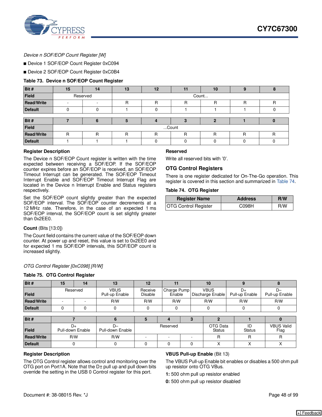
Table 75. OTG Control Register
Reserved
Write all reserved bits with ’0’.
OTG Control Registers
There is one register dedicated for
Table 74. OTG Register
Register Name | Address | R/W |
OTG Control Register | C098H | R/W |
|
|
|
Bit # | 15 |
| 14 | 13 | 12 | 11 | 10 | 9 | 8 |
Field | Reserved |
| VBUS | Receive | Charge Pump | VBUS | D+ | D– | |
|
|
| Disable | Enable | Discharge Enable | ||||
Read/Write | - |
| - | R/W | R/W | R/W | R/W | R/W | R/W |
Default | 0 |
| 0 | 0 | 0 | 0 | 0 | 0 | 0 |
|
|
|
|
|
|
|
|
|
|
Bit # | 7 | 6 | 5 | 4 | 3 | 2 | 1 | 0 |
Field | D+ | D– |
| Reserved |
| OTG Data | ID | VBUS Valid |
|
|
| Status | Status | Flag | |||
Read/Write | R/W | R/W | - | - | - | R | R | R |
Default | 0 | 0 | 0 | 0 | 0 | X | X | X |
|
|
|
|
|
|
|
|
|
Register Description
The OTG Control register allows control and monitoring over the OTG port on Port1A. Note that the D± pull up and pull down bits override the setting in the USB 0 Control register for this port.
VBUS Pull-up Enable (Bit 13)
The VBUS
1:500 ohm pull up resistor enabled
0:500 ohm pull up resistor disabled
Document #: | Page 48 of 99 |
[+] Feedback