Summit Family Switches Hardware Installation Guide
Summit Family Switches Hardware Installation Guide
Contents
Part 2 Installing the Hardware
Contents
Building a SummitStack Configuration
Installing Summit Family Switches
119
195
Installing Summit External Power Supplies
173
Summit Option Cards
215
203
Part 3 Appendices
227
Preface
Conventions
Related Publications
Text Conventions
About the Summit Family Switches
Page
Summit Family Switches
Overview of the Summit Switches
Summit Switch Features-Summit X150, X250e, and 350 Series
Summit Switch Features-Summit X450, X450a, and X450e Series
Summit Switch Features-Summit X480 and X650 Series
Feature Summit X480 Series Summit X650 Series
Summit Family Switches
Combination Ports and Failover
Summit X150 Series Switches
Summit X150-48t Switch
Summit X150-24t Switch
Summit X150-24t Switch Front Panel
Summit X150-24p Switch
Summit X150-24p Switch Front Panel
Summit X150-48t Switch
Summit X150-48t Switch Front Panel
Summit X150 Series Switch LEDs
LEDs on the Summit X150 Series Switches
Summit X250e Series Switches
Summit X250e-48p Switch
Summit X250e-24t Switch
Summit X250e-24t Switch Front Panel
Summit X250e-24tDC Switch
Summit X250e-24tDC Switch Front Panel
Summit X250e-24p Switch
Summit X250e-24tDC Switch Rear Panel
Summit X250e-24x Switch
Summit X250e-24p Switch Rear Panel
Summit X250e-24x Switch Front Panel
Summit X250e-24xDC Switch
Summit X250e-24xDC Switch Front Panel
Summit X250e-48t Switch
Summit X250e-24xDC Switch Rear Panel
Summit X250e-48tDC Switch
Summit X250e-48t Switch Rear Panel
Summit X250e-48tDC Switch Rear Panel
Summit X250e-48p Switch
Summit X250e-48p Switch Front Panel
External Power Supplies
Summit X250e-48p Power Supplies
Internal Power Supply
Power on
Summit X250e Series Switch LEDs
LEDs on the Summit X250e Series Switches
Port
Ports
Rear Panel Management
Stack Port
Summit X350 Series Switches
Summit X350-48t Switch
Summit X350-24t Switch
Summit X350-24t Switch Front Panel
Summit X350-48t Switch
Summit X350-24t Switch Rear Panel
Summit X350-48t Switch Rear Panel
Summit X350 Series Switch LEDs
LEDs on the Summit X350 Series Switches
Summit X450, X450a, and X450e Series Switches
Summit X450 Series Switches
Summit X450-24t Switch
Summit X450-24x Switch
Summit X450-24t Switch Rear Panel
Summit X450-24x Switch Rear Panel
Summit X450a Series Switches
Summit X450a-24t Switch
Summit X450a-24t Switch Front Panel
Summit X450a-24tDC Switch
Summit X450a-24tDC Switch Front Panel
Summit X450a-24x Switch
Summit X450a-24tDC Switch Rear Panel
Summit X450a-24x Switch Rear Panel
Summit X450a-24xDC Switch
Summit X450a-24xDC Switch Front Panel
Summit X450a-48t Switch
Summit X450a-24xDC Switch Rear Panel
Summit X450a-48tDC Switch
Summit X450a-48t Switch Rear Panel
Summit X450a-48tDC Switch Front Panel
Summit X450e Series Switches
Summit X450e-24p Switch
Summit X450e-24p Switch Rear Panel
Summit X450e-48p Switch
Summit X450e-48p Switch Front Panel
Summit X450e-48p Power Supplies
Summit X450e-48p Switch Rear Panel
Internal PSU Power On
Summit X450, X450a, and X450e Series Switch LEDs
LEDs on the Summit X450, X450a, and X450e Switches
Number of External PSUs and Corresponding PoE Behavior
45 48 are shared ports
Stack Number Indicator
24 or 1 48 21 -24
All front-panel ports
Summit X480 Series Switches
Summit X480-24x Switch
Summit X480-24x Switch Front Panel
Summit X480-48x Switch
Summit X480-48x Switch Front Panel
Summit X480-48t Switch
Summit X480-48t Switch Front Panel
Port Numbers for XFP Ports on the VIM2-10G4X Module
VIM2-SummitStack Versatile Interface Module
VIM2-10G4X Versatile Interface Module
VIM2-SummitStack128 Versatile Interface Module
VIM2-SummitStack128 Versatile Interface Module
Summit X480 Series Switch LEDs
LEDs on the Summit X480 Series Switches
Summit X650 Series Switches
Summit X650-24t Switch Summit X650-24x Switch
Summit X650-24t Switch
Summit X650-24t Front Panel
Summit X650-24x Switch
Summit X650-24x Front Panel
VIM1-SummitStack Versatile Interface Module
VIM1-10G8X Versatile Interface Module
VIM1-SummitStack512 Versatile Interface Module
VIM1-SummitStack256 Versatile Interface Module
Summit X650 Series Switch LEDs
LEDs on the Summit X650 Series Switches
Summit Switch and EPS Compatibility
Overview
Summit Power Supplies
EPS-160 External Power Module with EPS-T
EPS-LD External Power Supply Unit
EPS-500 External Power Supply Unit
EPS-150DC External Power Module with EPS-T2
Single 600-LS Module Configuration Redundant PoE Power
EPS-600LS External Power Module
PoE Redundant Power Configurations
External Power Modules and Corresponding PoE Behavior
Internal-to-External PSU Transfer
Dual 600-LS Module Configuration Full Power
Triple 600-LS Module Configuration Full Redundant Power
External-to-Internal PSU Transfer
Summit X480 Power Supplies
Example Two active EPS-600LS modules in an EPS-C
Summit X650 Power Supplies
Installing the Hardware
Page
Site Preparation
Planning Your Site
Building and Electrical Codes
Meeting Site Requirements
Operating Environment Requirements
Wiring Closet Considerations
Temperature
Spacing Requirements and Airflow
Rack Specifications and Recommendations
Humidity
Electrostatic Discharge
Space Requirements for the Rack
Mechanical Recommendations for the Rack
Protective Grounding for the Rack
Securing the Rack
Evaluating and Meeting Cable Requirements
Cabling Standards
Installing Cable
Cable Labeling and Record Keeping
Properly Installed and Bundled Cable
Fiber Optic Cable
Cable Distances
Media Types and Maximum Distances
RJ-45 Connector Jackets
Radio Frequency Interference
AC Power Cables
Meeting Power Requirements
Power Supply Requirements
PoE Devices
Calculating Volt-Amperage Requirements
Uninterruptible Power Supply Requirements
Selecting a UPS
UPS Transition Time
DC Power Requirements
Applicable Industry Standards
Site Preparation
Stacking Summit Family Switches
Summit Switches Connected in a SummitStack Configuration
Slot Numbers
About Redundancy
Stacking Cables
Available Stacking Cables
Placing Summit Family Switches for Stacked Operation
Single-Rack Stacking Configurations
Connecting the Switches to Form the Stack Ring
Using SummitStack Ports and 40G Stacking Cables
Recommended Order for Stacking Connections 4-Switch Stack
Recommended Order for Stacking Connections 8-Switch Stack
Multiple-Rack Stacking Configurations
104
Top-of-Rack Stack Installation
Combining Different Types of Stacking Ports
Combining Stacking Port Types
Using the VIM1-SummitStack512 Module
Connecting Stacking Cables
Connecting a SummitStack 40G Cable to a Stacking Port
Connecting a SummitStack 128G Cable
Cable Management Using a J-Shaped Support Bracket
Connecting a SummitStack 128G Cable
Connecting a SummitStack 128G/20G Stacking Cable
Connecting the 128G Connector
Connecting the 20G Connector
Connecting a SummitStack 128G/64G Stacking Cable
Cable Management Using Tie-Wraps and Stand-Offs
Connecting the 128G/64G Cable
Connecting a SummitStack 64G Stacking Cable
Connecting a SummitStack 64G Cable
Connecting a SummitStack 64G/20G Stacking Cable
Connecting the 64G Connector
Stacking Port LEDs
Connecting Console Ports for a Stack
Management Port Cabling
Installing Summit Family Switches
Safety Information
Installing Summit Family Switches
Attaching the Mounting Bracket
Free-Standing and Desktop Mounting of Multiple Switches
Installing and Removing Summit DC-Powered Switches
Grounding a Summit DC-Powered Switch
Location of the Grounding Lug
Connecting the DC Wiring Harness to the DC Source Voltage
Three-wire Cable Harness
Removing a Summit DC-Powered Switch from a Rack
DC Power Socket on a Summit X250e Series DC-Powered Switch
Installing a Summit X480 Series Switch
Pre-installation Requirements
Mid-Mounting the Switch in a Two-Post Rack
Selecting Rear Mounting Brackets
Sliding the Switch onto the Rear Mounting Brackets
Positioning the Front Mounting Brackets
Front-Mounting the Switch in a Two-Post Rack
Attaching a Front Mounting Bracket
Installing the Switch in a Four-Post Rack
Attaching Rear Mounting Brackets-Four-Post Installation
Installing the Switch-Four-Post Installation
Installing Summit X480 Power Supplies
AC Power Supply Cords
Installing a Summit X480 AC PSU
Removing a Blank Panel
Installing a Summit X480 DC Power Supply
Installing a PSU
Required Tools and Materials
Preparing the Cables
Installing the Power Supply
Attaching a Terminal to a Cable
Connecting the Ground Wire
Installing a DC PSU
Connecting the Ground Wire
Connecting the PSU to the DC Source Voltage
Securing the Ground Wire
Connecting the DC Power Cables Part
Removing a Summit X480 Series Switch
Removing the Power Supplies
Removing a Summit X480 AC Power Supply
Removing a Summit X480 DC Power Supply
Removing a Mid-Mounted Switch from a Two-Post Rack
Removing a DC PSU
Removing a Mid-Mounted Switch from a Two-Post Rack
Removing a Front-Mounted Switch from a Two-Post Rack
Removing the Rear Mounting Brackets
Removing a Switch from a Four-Post Rack
Removing a Front-Mounted Switch from a Two-Post Rack
Installing a Summit X650 Series Switch
Removing the Switch from a Four-Post Rack
Installing the Switch in a Two-Post Rack
Attaching a Rear Mounting Bracket-Two-Post Rack Installation
Fastening the Rear Mounting Brackets-Two-Post Rack
Positioning the Front Mounting Brackets-Two-Post Rack
Installing the Switch in a Cabinet or Four-Post Rack
Attaching Rear Mounting Brackets-Cabinet Installation
Attaching the Front Mounting Brackets-Cabinet Installation
Installing Summit X650 Power Supplies
Installing a Summit X650 AC Power Supply
Installing a Summit X650 DC Power Supply
To install a second PSU, repeat steps 3
159
Attaching Terminals to Cables
Connecting the Ground Cable
Installing a Summit X650 DC PSU
162
163
Removing a Summit X650 Series Switch
Removing a Summit X650 AC Power Supply’
Removing a DC Power Supply
Removing a Summit X650 Series Switch from a Two-Post Rack
Removing the Front Mounting Screws from a Two-Post Rack
Removing the Rear Mounting Brackets-Two-Post Rack
Connecting Network Interface Cables
Cable Distances for 10GBASE-T Ports
Initial Management Access
Connecting Equipment to the Console Port
Logging In for the First Time
172
Installing Summit External Power Supplies
Safety
Pre-installation Requirements
Installing an EPS-160 External Power Module with EPS-T
Installing an EPS-160 Power Supply into an EPS-T
Rack-Mounting the EPS-T
Connecting the EPS-160 Power Supply to the Switch
Redundant Power Connections
LED Meanings on the EPS-160 Power Supply
Installing an EPS-LD External Power Supply
Removing an EPS-160 Power Supply from an EPS-T
Rack-mounting the EPS-LD Power Supply
Connecting the EPS-LD to the Switch
EPS-LD Connector with Key
Removing an EPS-LD
Installing an EPS-500 External Power Supply Unit
Connecting the EPS-LD to Power
LED Meanings on the EPS-LD
Rack-mounting an EPS-500 Power Supply
Attaching a Mounting Bracket
Connecting the EPS-500 Power Supply
EPS-500 Redundant Power Cord with Connector Key
LED Meanings on the EPS-500 Power Supply
Installing an EPS-150DC External Power Module with EPS-T2
Removing an EPS-500 Power Supply
Rack-mounting the EPS-T2
Installing an EPS-150DC Power Supply
Installing an EPS-150DC Unit into an EPS-T2
186
Connecting the EPS-150DC to a Switch
Connecting the Input Cable to the EPS-150DC Unit
Removing an EPS-150DC Power Module
LED Meanings on the EPS-150DC Power Supply
Installing an EPS-600LS External Power Module
Installing an EPS-C Chassis
EPS-C and Summit Switch
Installing an EPS-600LS Power Supply
Installing the Redundant Power Cord
Installing the EPS-600LS Unit in the EPS-C Chassis
Removing an EPS-600LS Power Module
194
Summit Option Cards
Summit XGM-2xn Option Card
Summit X450 ZR Xenpak Combinations
Summit XGM2-2xn Option Card
Mixing ZR XENPAKs with Other Types
Summit XGM2-2xf Option Card
Summit XGM2-2xn Option Card
Cable Distances for the XGM2-2bt Option Card
Summit XGM2-2sf Option Card
Summit XGM2-2bt Option Card
Installing a Summit Port Option Card
Option Slot Filler Panel
Installing a Summit Port Option Card XGM-2xn Shown
202
Replacing a Summit X650 AC PSU
Installing an AC PSU
Replacing a Summit X650 DC Power Supply
Removing the PSU
Installing the Replacement PSU
Connecting the Ground Wire
Connecting the DC Power Cables
208
209
Removing a Fan Module Summit X650 Series Switch Shown
Replacing a Summit X480/X650 Fan Module
Replacing a Versatile Interface Module VIM
Removing a VIM VIM1-SummitStack Module Shown
Installing a VIM1 Module VIM1-SummitStack Module Shown
Appendices
Page
Safety Information
Considerations Before Installing
Installing External Power Supply Units
Cable Routing for LAN Systems
Maintenance Safety
General Safety Precautions
Selecting Power Supply Cords
218
Battery Replacement and Disposal
Fiber Optic Ports-Optical Safety
SFP Mini-GBIC, XENPAK, and XFP Regulatory Compliance
Hinweise zur Installation
Sicherheitshinweise
Installation von Netzteilen
222
Wartungssicherheit
Allgemeine Sicherheitsvorkehrungen
Auswahl der Stromkabel
Austauschen und Entsorgen von Batterien
Lichtleiteranschlüsse Optische Sicherheit
226
Weight
Summit X150 Series Switch Technical Specifications
Physical Dimensions
Summit X150-24t Power
Packaged Dimensions
Packaged Weight
Summit X150-24p Power
EMI/EMC Standards
Summit X150-48t Power
Safety Standards
230
Summit X250e Series Switch Technical Specifications
Summit X250e-24x Power
Summit X250e-24t Power
Summit X250e-24p Power
Summit X250e-24xDC Power
Summit X250e-24tDC Power
Summit X250e-48t Power
Summit X250e-48p Power
Summit X250e-48tDC Power
236
Summit X350-48t Power
Summit X350 Series Switch Technical Specifications
Summit X350-24t Power
Telecom Standards
239
Power
Summit X450 Series Switches
Summit X450 Series Switch Technical Specifications
241
Summit X450a-24t Power
Summit X450a Series Switches
Summit X450a Series Switch Technical Specifications
Summit X450a-48tDC Power
Summit X450a-24tDC Power
Summit X450a-48t Power & Acoustic Sound
Summit X450a-24xDC Power
245
Summit X450e-24p Power
Summit X450e Series Switches
Summit X450e Series Switch Technical Specifications
Summit X450e-48p Power
247
248
Summit X480 Series Switch Technical Specifications
Fan Speed
Summit X480-24x with VIM2-10G4X Module DC Power Supply
Summit X480-24x with VIM2-10G4X Module AC Power Supply
Summit X480-24x with No Installed VIM DC Power Supply
Summit X480-48x with VIM2-10G4X Module AC Power Supply
Summit X480-48t with VIM2-10G4X Module AC Power Supply
Summit X480-48x with No Installed VIM DC Power Supply
Summit X480-48x with VIM2-10G4X Module DC Power Supply
Summit X480-48t with No Installed VIM DC Power Supply
Summit X480-48t with VIM2-SummitStack Module DC Power Supply
Summit X480-48t with VIM2-10G4X Module DC Power Supply
Summit X480 AC PSU Model
Physical Specifications
Power Specifications
Environmental Specifications
Summit X480 DC PSU Model
Summit X650 Series Switch Technical Specifications
Summit X650-24t with VIM1-10G8X Module AC Power Supply
Summit X650-24t with VIM1-10G8X Module DC Power Supply
Summit X650-24x with VIM1-10G8X Module AC Power Supply
Summit X650-24x with VIM1-10G8X Module DC Power Supply
258
259
Summit X650 AC PSU Model
Summit X650 DC PSU Model
EPS-160 External Power Module Model
Summit External Power Supplies
EPS-LD External Power Supply Model
Pinouts for the Redundant Power Supply Connector
EPS-500 External Power Supply Model
263
Efficiency
EPS-600LS External Power Module Model
Maximum inrush current
Three EPS-600-LS units
EPS-150DC External Power Module Model
Wire-to-Pin Connection Specifications
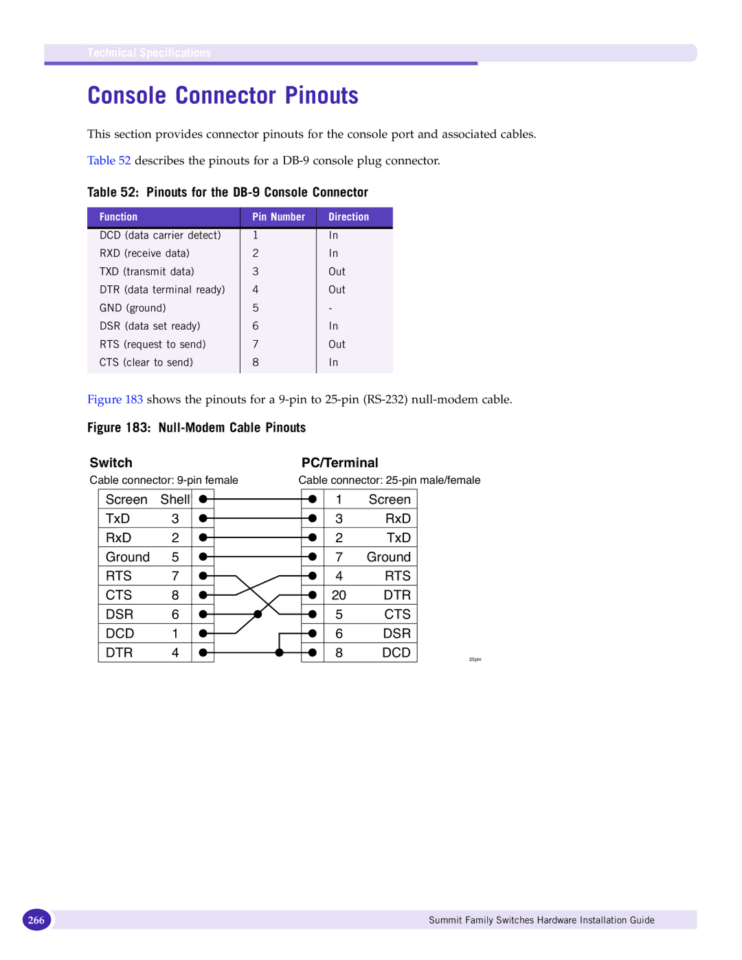
Console Connector Pinouts
Pinouts for the DB-9 Console Connector
PC-AT Serial Null-modem Cable Pinouts Switch PC/Terminal
268
Index
Index
271
272
VIM
XGM2-2xn option card XGM-2xn option card