Advanced Operations
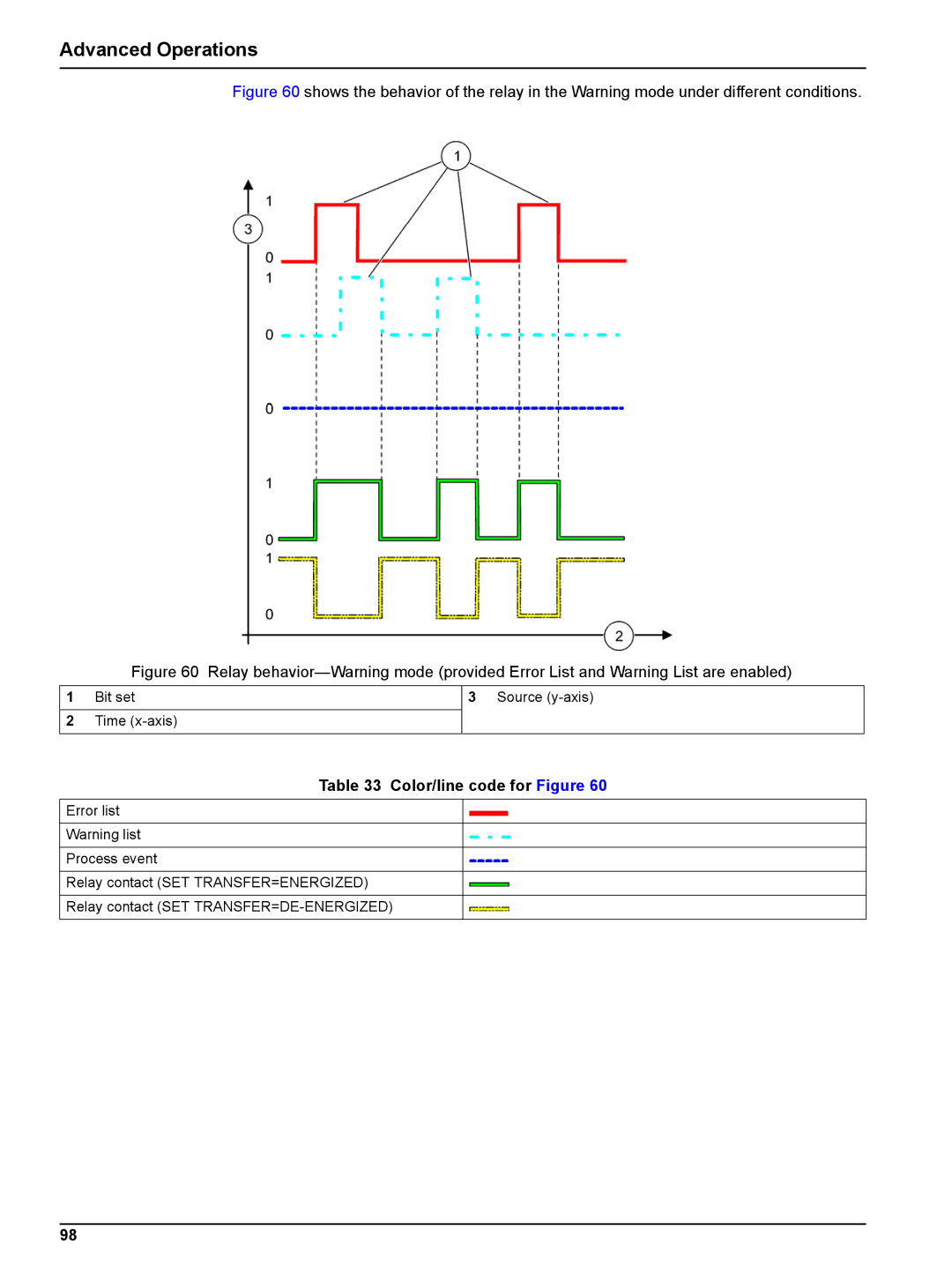
Figure 60 shows the behavior of the relay in the Warning mode under different conditions.
Figure 60 Relay behavior—Warning mode (provided Error List and Warning List are enabled)
1Bit set
2Time (x-axis)
3Source (y-axis)
Table 33 Color/line code for Figure 60
Error list
Warning list
Process event
Relay contact (SET TRANSFER=ENERGIZED)
Relay contact (SET
98