Installation
9.If necessary, set the terminating resistor.
Note: When using the connector with the last module on the network segment, one union nut remains unused. Seal the union nut with the plug supplied. Refer to Figure 31.
10.If this connector is the end of the network, insert the rubber seal in the connector.
11.Tighten the union nut by two turns.
12.Insert the sealing plug in the unused union nut and rubber seal.
13.Tighten the union nut.
14.Set a terminating resistor at the last network connector to the ON position (see Figure 32 and Table 11).
15.Plug the connector into the probe module.
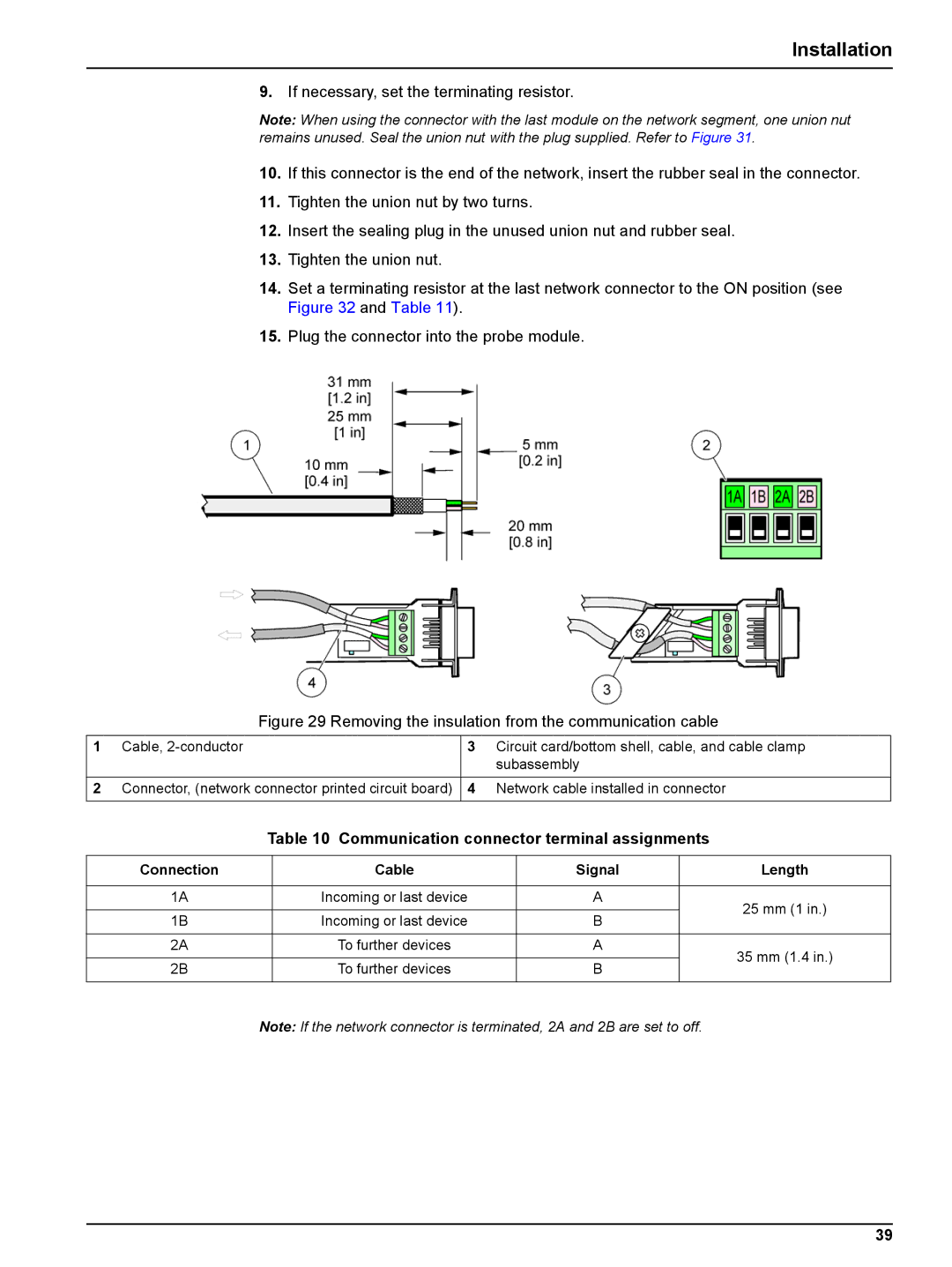
Figure 29 Removing the insulation from the communication cable
1 | Cable, | 3 | Circuit card/bottom shell, cable, and cable clamp |
|
|
| subassembly |
|
|
|
|
2 | Connector, (network connector printed circuit board) | 4 | Network cable installed in connector |
|
|
|
|
Table 10 Communication connector terminal assignments
Connection | Cable | Signal | Length | |
|
|
|
| |
1A | Incoming or last device | A | 25 mm (1 in.) | |
|
|
| ||
1B | Incoming or last device | B | ||
| ||||
|
|
|
| |
2A | To further devices | A | 35 mm (1.4 in.) | |
|
|
| ||
2B | To further devices | B | ||
| ||||
|
|
|
|
Note: If the network connector is terminated, 2A and 2B are set to off.
39