General Information
2.1.2 Precautionary labels
Read all labels and tags attached to the instrument. Personal injury or damage to the instrument could occur if not observed
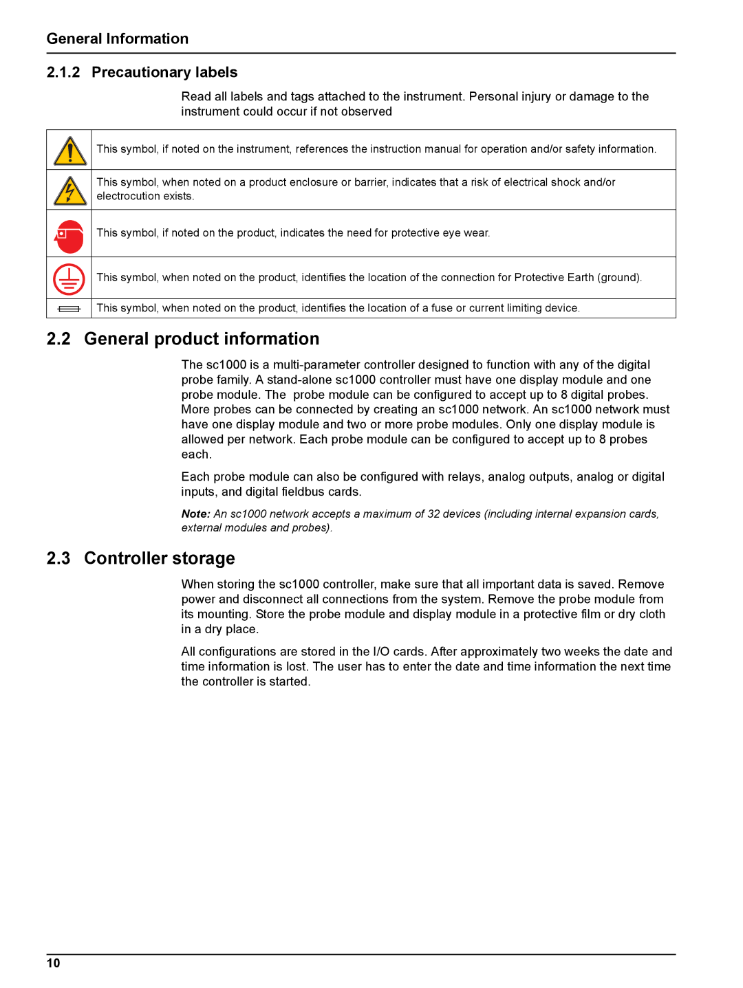
This symbol, if noted on the instrument, references the instruction manual for operation and/or safety information.
This symbol, when noted on a product enclosure or barrier, indicates that a risk of electrical shock and/or electrocution exists.
This symbol, if noted on the product, indicates the need for protective eye wear.
This symbol, when noted on the product, identifies the location of the connection for Protective Earth (ground).
This symbol, when noted on the product, identifies the location of a fuse or current limiting device.
2.2 General product information
The sc1000 is a
More probes can be connected by creating an sc1000 network. An sc1000 network must have one display module and two or more probe modules. Only one display module is allowed per network. Each probe module can be configured to accept up to 8 probes each.
Each probe module can also be configured with relays, analog outputs, analog or digital inputs, and digital fieldbus cards.
Note: An sc1000 network accepts a maximum of 32 devices (including internal expansion cards, external modules and probes).
2.3 Controller storage
When storing the sc1000 controller, make sure that all important data is saved. Remove power and disconnect all connections from the system. Remove the probe module from its mounting. Store the probe module and display module in a protective film or dry cloth in a dry place.
All configurations are stored in the I/O cards. After approximately two weeks the date and time information is lost. The user has to enter the date and time information the next time the controller is started.
10