Advanced Operations
6.3.2 Current inputs menu
Note: The menus appear only if an input card is installed in the sc1000 controller.
The current input card can be used as an analog input card to measure an input current in a range from
ANALOG CURRENT INPUT
The current input card connects devices with a current input interface to the sc1000 controller. Every current input channel can be configured separately, unit and parameter are displayed in the measured value display. It is mandatory to have an corresponding open jumper on the current input card to connect a device.
DIGITAL CURRENT INPUT
To differ two digital states the corresponding jumper on the internal current input card has to be closed respectively the corresponding bridge has to be set at the external current input card. The different states are recognized by closing or opening a contact between the corresponding screwing terminals.
There is the possibility to adjust the input current measuring with an offset and a correction factor to enhance the accuracy. By default these two parameters are set to “0” (offset) and “1” (correction factor). When a channel is used as a digital input the display will show the values “HIGH” or “LOW”.
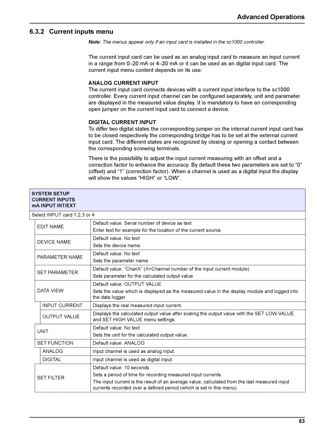
SYSTEM SETUP CURRENT INPUTS mA INPUT INT/EXT
Select INPUT card 1,2,3 or 4
| EDIT NAME | Default value: Serial number of device as text | |
| Enter text for example for the location of the current source. | ||
|
|
| |
|
|
|
|
| DEVICE NAME | Default value: No text | |
| Sets the device name. | ||
|
|
| |
|
|
|
|
| PARAMETER NAME | Default value: No text | |
| Sets the parameter name. | ||
|
|
| |
|
|
|
|
| SET PARAMETER | Default value: “ChanX” (X=Channel number of the input current module) | |
| Sets parameter for the calculated output value. | ||
|
|
| |
|
|
|
|
|
|
| Default value: OUTPUT VALUE |
| DATA VIEW | Sets the value which is displayed as the measured value in the display module and logged into | |
|
|
| the data logger. |
|
|
|
|
|
| INPUT CURRENT | Displays the real measured input current. |
|
|
|
|
|
| OUTPUT VALUE | Displays the calculated output value after scaling the output value with the SET LOW VALUE |
|
| and SET HIGH VALUE menu settings. | |
|
|
| |
|
|
|
|
| UNIT | Default value: No text | |
| Sets the unit for the calculated output value. | ||
|
|
| |
|
|
| |
| SET FUNCTION | Default value: ANALOG | |
|
|
|
|
|
| ANALOG | Input channel is used as analog input. |
|
|
|
|
|
| DIGITAL | Input channel is used as digital input. |
|
|
|
|
|
|
| Default value: 10 seconds |
| SET FILTER | Sets a period of time for recording measured input currents. | |
| The input current is the result of an average value, calculated from the last measured input | ||
|
|
| |
|
|
| currents recorded over a defined period (which is set in this menu). |
|
|
|
|
83