Installation
To make a relay card connection
For instruments not equipped with a relay card, do the steps listed below to make relay card connections.
1.Remove power from the instrument. Remove the probe module cover.
2.Remove the screws on the plastic relay cover. Remove the plastic cover.
3.Connect the relay card to the appropriate slot (Figure 18). Use a magnetic screwdriver to secure the four
4.Install the card connector to the appropriate connection on the main circuit board (Figure 17).
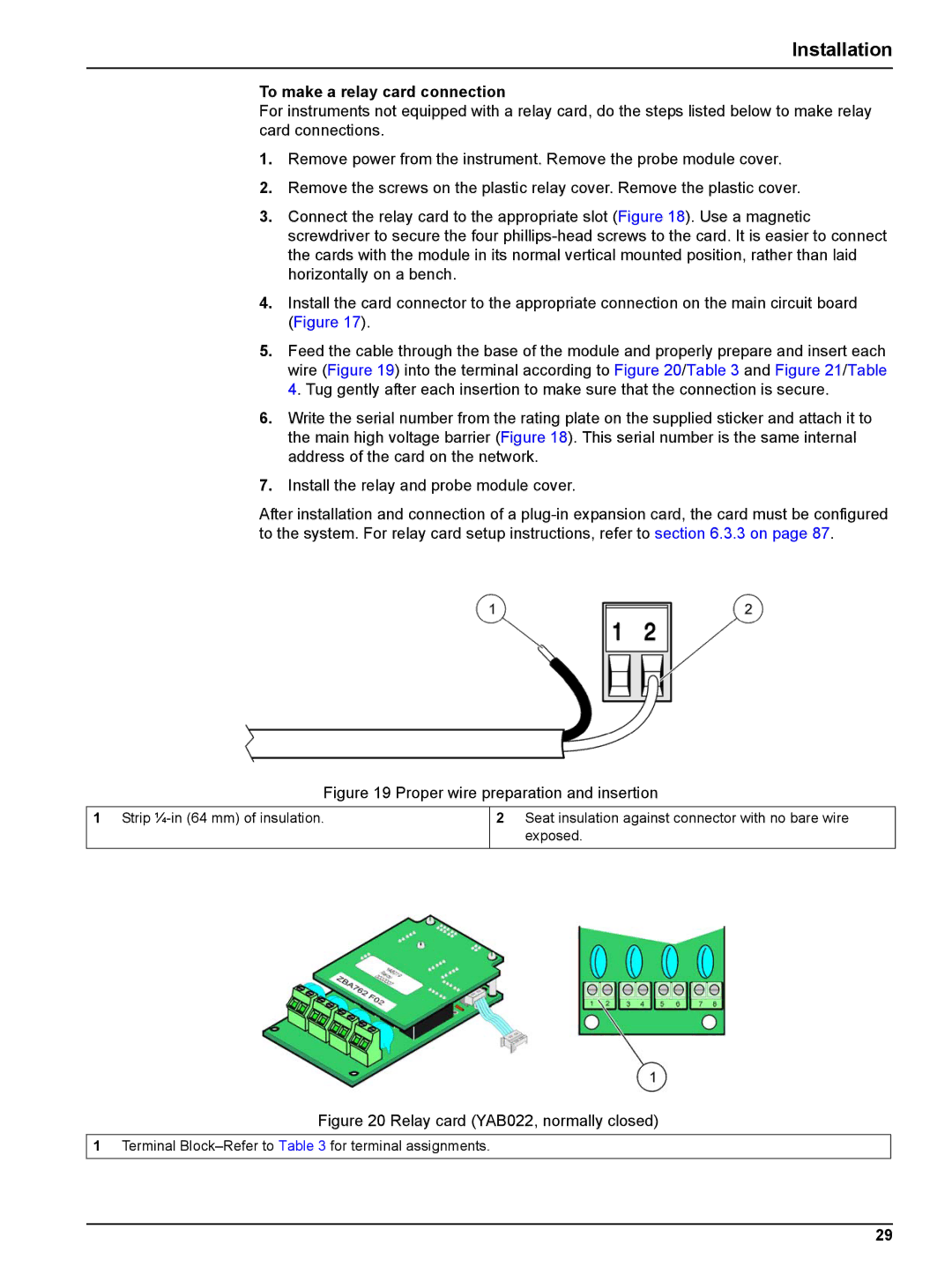
5.Feed the cable through the base of the module and properly prepare and insert each wire (Figure 19) into the terminal according to Figure 20/Table 3 and Figure 21/Table 4. Tug gently after each insertion to make sure that the connection is secure.
6.Write the serial number from the rating plate on the supplied sticker and attach it to the main high voltage barrier (Figure 18). This serial number is the same internal address of the card on the network.
7.Install the relay and probe module cover.
After installation and connection of a
Figure 19 Proper wire preparation and insertion
1Strip
2Seat insulation against connector with no bare wire exposed.
Figure 20 Relay card (YAB022, normally closed)
1Terminal
29