Figure 74 Attaching multiple expansion modules
A.3 Attach the base module
The base module provides a connection for a display module and contains a connection and the terminating resistor for the sc1000 network. The LED on the front indicates the status of the network communication.
The base module is required for any additional modules.
Prior to installing the base module, make sure the DIN rail is mounted correctly and that all safety requirements are met.
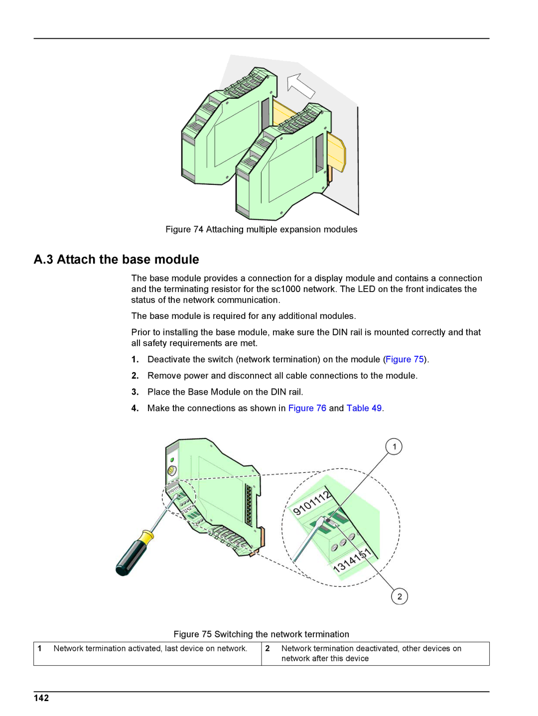
1.Deactivate the switch (network termination) on the module (Figure 75).
2.Remove power and disconnect all cable connections to the module.
3.Place the Base Module on the DIN rail.
4.Make the connections as shown in Figure 76 and Table 49.
Figure 75 Switching the network termination
1Network termination activated, last device on network.
2Network termination deactivated, other devices on network after this device
