Advanced Operations
6.3.4.2 Modbus
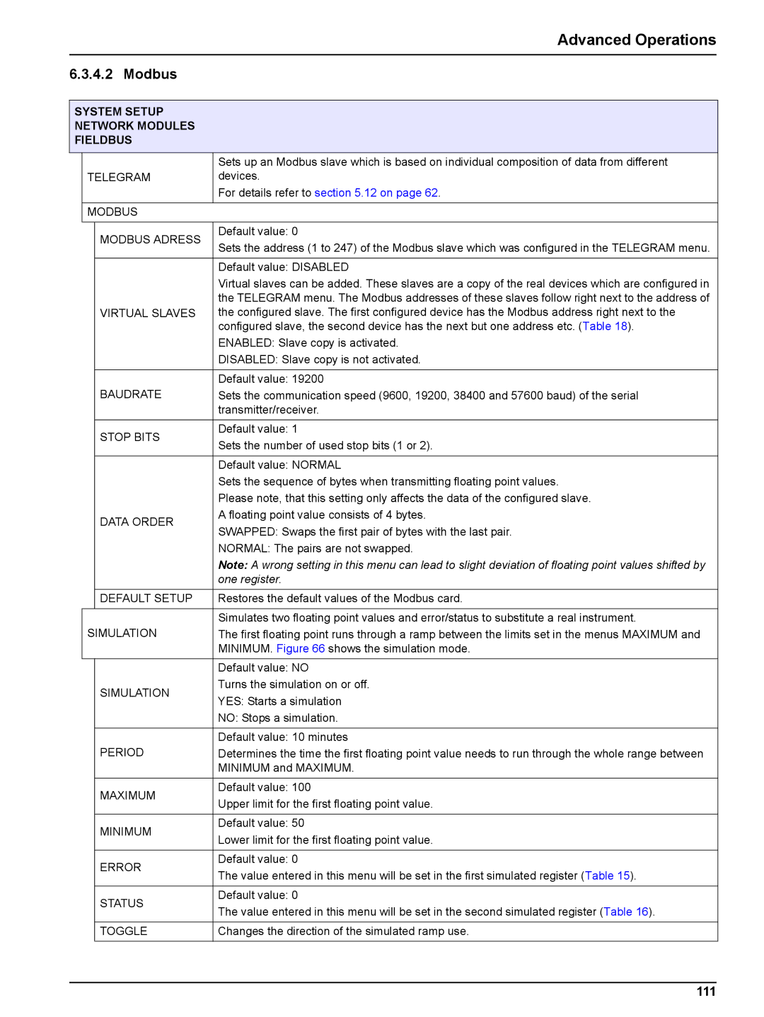
SYSTEM SETUP
NETWORK MODULES
FIELDBUS
|
|
| Sets up an Modbus slave which is based on individual composition of data from different |
| TELEGRAM | devices. | |
|
|
| For details refer to section 5.12 on page 62. |
|
|
| |
| MODBUS |
| |
|
|
|
|
|
| MODBUS ADRESS | Default value: 0 |
|
| Sets the address (1 to 247) of the Modbus slave which was configured in the TELEGRAM menu. | |
|
|
| |
|
|
|
|
|
|
| Default value: DISABLED |
|
|
| Virtual slaves can be added. These slaves are a copy of the real devices which are configured in |
|
|
| the TELEGRAM menu. The Modbus addresses of these slaves follow right next to the address of |
|
| VIRTUAL SLAVES | the configured slave. The first configured device has the Modbus address right next to the |
|
|
| configured slave, the second device has the next but one address etc. (Table 18). |
|
|
| ENABLED: Slave copy is activated. |
|
|
| DISABLED: Slave copy is not activated. |
|
|
|
|
|
|
| Default value: 19200 |
|
| BAUDRATE | Sets the communication speed (9600, 19200, 38400 and 57600 baud) of the serial |
|
|
| transmitter/receiver. |
|
|
|
|
|
| STOP BITS | Default value: 1 |
|
| Sets the number of used stop bits (1 or 2). | |
|
|
| |
|
|
|
|
|
|
| Default value: NORMAL |
|
|
| Sets the sequence of bytes when transmitting floating point values. |
|
|
| Please note, that this setting only affects the data of the configured slave. |
|
| DATA ORDER | A floating point value consists of 4 bytes. |
|
| SWAPPED: Swaps the first pair of bytes with the last pair. | |
|
|
| |
|
|
| NORMAL: The pairs are not swapped. |
|
|
| Note: A wrong setting in this menu can lead to slight deviation of floating point values shifted by |
|
|
| one register. |
|
|
|
|
|
| DEFAULT SETUP | Restores the default values of the Modbus card. |
|
|
|
|
|
|
| Simulates two floating point values and error/status to substitute a real instrument. |
| SIMULATION | The first floating point runs through a ramp between the limits set in the menus MAXIMUM and | |
|
|
| MINIMUM. Figure 66 shows the simulation mode. |
|
|
|
|
|
|
| Default value: NO |
|
| SIMULATION | Turns the simulation on or off. |
|
| YES: Starts a simulation | |
|
|
| |
|
|
| NO: Stops a simulation. |
|
|
|
|
|
|
| Default value: 10 minutes |
|
| PERIOD | Determines the time the first floating point value needs to run through the whole range between |
|
|
| MINIMUM and MAXIMUM. |
|
|
|
|
|
| MAXIMUM | Default value: 100 |
|
| Upper limit for the first floating point value. | |
|
|
| |
|
|
|
|
|
| MINIMUM | Default value: 50 |
|
| Lower limit for the first floating point value. | |
|
|
| |
|
|
|
|
|
| ERROR | Default value: 0 |
|
| The value entered in this menu will be set in the first simulated register (Table 15). | |
|
|
| |
|
|
|
|
|
| STATUS | Default value: 0 |
|
| The value entered in this menu will be set in the second simulated register (Table 16). | |
|
|
| |
|
|
|
|
|
| TOGGLE | Changes the direction of the simulated ramp use. |
|
|
|
|