Installation
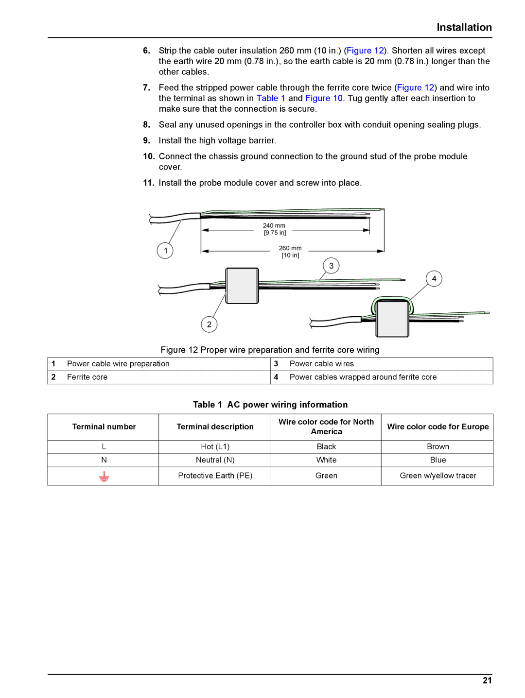
6.Strip the cable outer insulation 260 mm (10 in.) (Figure 12). Shorten all wires except the earth wire 20 mm (0.78 in.), so the earth cable is 20 mm (0.78 in.) longer than the other cables.
7.Feed the stripped power cable through the ferrite core twice (Figure 12) and wire into the terminal as shown in Table 1 and Figure 10. Tug gently after each insertion to make sure that the connection is secure.
8.Seal any unused openings in the controller box with conduit opening sealing plugs.
9.Install the high voltage barrier.
10.Connect the chassis ground connection to the ground stud of the probe module cover.
11.Install the probe module cover and screw into place.
Figure 12 Proper wire preparation and ferrite core wiring
1 | Power cable wire preparation | 3 | Power cable wires |
|
|
|
|
2 | Ferrite core | 4 | Power cables wrapped around ferrite core |
|
|
|
|
Table 1 AC power wiring information
Terminal number | Terminal description | Wire color code for North | Wire color code for Europe | |||||||
America | ||||||||||
|
|
|
|
|
|
|
|
| ||
|
|
|
|
|
|
|
|
|
| |
|
| L | Hot (L1) | Black | Brown | |||||
|
|
|
|
|
|
|
|
|
| |
|
| N | Neutral (N) | White | Blue | |||||
|
|
|
|
|
|
|
|
|
| |
|
|
|
|
|
|
| Protective Earth (PE) | Green | Green w/yellow tracer | |
|
|
|
|
|
|
| ||||
|
|
|
|
|
|
|
|
|
| |
21