Manuals
/
Hach
/
Computer Equipment
/
Network Card
Hach
sc1000
user manual
Display module, 135
Models:
sc1000
1
137
150
150
Download
150 pages
30.78 Kb
134
135
136
137
138
139
140
141
Troubleshooting
Specifications
Install
Connection Cable Signal Length
Error and status register
MAX Timer Expire
Wiring safety information
Warranty
Dimension
Maintenance
Page 137
Image 137
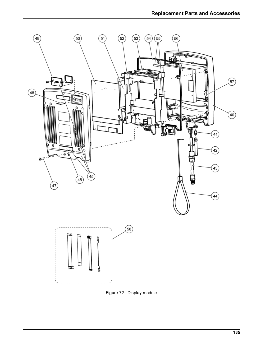
Replacement Parts and Accessories
Figure 72 Display module
135
Page 136
Page 138
Page 137
Image 137
Page 136
Page 138
Contents
Sc1000 controller
Page
Table of Contents
Table of Contents
Section
Table of Contents
Table of Contents
Probe Module
Section Specifications
Display Module
Plug-in Expansion Cards
Specifications
DIN Rail Switch Cabinet Expansion Modules
Certifications
Warranty
Specifications
Use of hazard information
Safety information
General Information
Controller storage
General Information Precautionary labels
General product information
Mechanical installation
Section Installation
Sc1000 controller dimensions
Installation Controller dimensions
Wall mounting
Installation
Mounting the controller
Installation Vertical or horizontal pipe mounting
Wiring safety information
Panel Mounting
Sun-shield
Remove display module and probe module cover
Electrostatic discharge ESD considerations
Installation in hard-wired applications
Electrical installation
Using the optional strain relief and conduit plug
Installation Installation using a power cord
Removing the probe module cover
Wiring for power
Inside the AC probe module
Wiring for AC power at the controller
AC power wiring information
Proper wire preparation and ferrite core wiring
Hard-wired installation
Installation with power cord
Inside the 24 VDC probe module
Installation Wiring for 24 VDC power at the controller
DC power wiring information
Wiring for 24 VDC power
DIN rail expansion modules
Expansion card main circuit board connections
Expansion cards
Expansion card ports
Relay card connections
To make a relay card connection
Proper wire preparation and insertion
Terminal Designation Relay
Relay card YAB022, normally closed terminal assignments
To make an input card connection
Input card connections
Relay card YAB076, change over terminal assignments
Input card YAB018 terminal assignments
Input card YAB018 cable connections and jumper setting
Output card YAB019 terminal assignments
Installation Output card connections
To make an output card connection
Modbus RS485 card YAB021 terminal assignments
Installation Modbus card connections
To make a Modbus card connection
Modbus RS232 card YAB047 terminal assignments
Profibus DP card connections
To make a Profibus card connection
Modbus RS232 designation
Terminal Designation
Profibus DP card YAB020 terminal assignments
To remove/replace an expansion card
Install an sc1000 network sc1000 bus connection
Installation Remove/Replace an expansion card
1 sc1000 network connections
To attach a network connector
Network Connector Assembly
Connection Cable Signal Length
Communication connector terminal assignments
Network connector components
Installation
Switch setting Terminating resistors Connection
Setting a terminating resistor DIP switch in the connector
Connect the probe data cable
Connect probes to the sc1000 controller
Installation Add probe connections
Service port connection LAN connection
Connect AC powered sc probes
To connect AC powered probes to a probe module
Safety precautions for GSM modem installation
Safety precautions
GSM modem connection
GSM modem requirements
SIM card requirements
Safety precautions for SIM card installation
Safety precautions for antenna installation
To insert the SIM card into the display module
Installation Insert the SIM card into the display module
Connect the external GSM antenna
To connect an external GSM antenna
To insert the storage card into the display module Figure
Storage card SD card
Insert the storage card into the display module
Content
Installation Prepare the storage card
To prepare the storage card
Storage card, folder structure
System Start Up
System Start Up
Attach the display module to the probe module
Standard Operations
Display module
Display modes
Standard Operations
Tips for the use of the touch screen
To view several measured values
Measured value display
To configure the measurement value display
Configure the measured value display
Graph display
Standard Operations Daily and weekly trend lines
Graph display
Main menu display
Calibrate the touch screen
Alphanumeric keypad
Specify the displayed language
To calibrate the touch screen after initial commissioning
Set the passcode
Set up system security passcode protection
Set the time and date
Add new components
Add and remove favorites
To add a favorite item
To remove a favorite item
To configure a Profibus/Modbus card
Configure the network modules Profibus/Modbus cards
Configure the Profibus/Modbus card
Profibus/Modbus configuration menu-Select tag
Error register
Error and status register
Bit Error Description
Telegram list-Column description
Bit Status Description
Status register-Status
Profibus configuration example
Standard Operations Profibus/Modbus configuration example
Modbus configuration example with virtual slaves
Profibus Slave Byte Device Data name Address
Set up the LAN connection
Remote control
To change the computer network card settings to 10BaseT
Prepare the LAN connection
To set the sc1000 controller settings
Set up the dial-up connection
To add a fixed IP address to the computer
General tab select Use the following IP address radio box
New connection wizard-Settings
To set computer settings description for Windows XP
Dialog box Setting
To run the dial-up connection and start the web browser
Button Function
To access an sc1000 controller through a web browser
Browser access screen-Navigation keys
To save log files through browser access
Save log files through browser access
Log data
Save log files to the storage card
To remove log files through browser access
Standard Operations Remove log files through browser access
Formula editor for output and relay card
Formula settings
Add a formula
To add a formula
Add a formula with measurement values from other probes
Formula settings-Example
Formula operations
Load
Formula editor-Mathematical functions
Formula editor-Arithmetic operations
Formula editor-Logical operations
Chka
Check functions to set errors and warnings
Advanced Operations
Sensor setup menu
Sensor status menu
Sensor Status
Advanced Operations
System setup menu
Output setup menu
System Setup Output Setup mA Output INT/EXT
Integral
Proportional
Derivative
Snap Shot
HV-LV
Relation between input current and calculated concentration
Output current with an output range of 4-20mA
Advanced Operations Current inputs menu
System Setup Current Inputs mA Input INT/EXT
Concentration
Logic
OFF
⋅ HV-LV
Output value with an input range of 0-20 mA
HV-LV ⋅
Output value with an input range of 4-20 mA
Advanced Operations Relay menu
General relay settings available in all relay working modes
System Setup Relay Relay INT/EXT
Alarm
Function set to Alarm working mode
Color/line code for Figure
Relay behavior-Alarm mode
Feeder Control
Function set to Feeder Control working mode
Advanced Operations
Relay behavior-Feeder Control mode Phase low, OnMax Timer
Point Control
Function set to 2 Point Control working mode
MAX Timer Expire
MIN Timer Expire
Relay behavior-2 Point Control mode without delay
Relay behavior-2 Point Control mode OnMin Timer, OnMax Timer
Relay behavior-2 Point Control mode ON/OFF delay
Process Event
Function set to Warning working mode
Bit set Time x-axis Source y-axis
PWM CONTROL/LINEAR
Function set to PWM CONTROL/LINEAR working mode
Linear
Duty Cycle
100
PWM Control/Linear mode-Maximum value
101
Relay behavior-PWM Control/Linear mode
PWM CONTROL/PID Control
Function set to PWM CONTROL/PID Control working mode
102
FREQ. Control / Linear
Function set to FREQ. Control / Linear working mode
103
104
Relay behavior-FREQ. Control/Linear mode
FREQ. Control /PID Control
Function set to FREQ. Control/PID Control mode
105
106
Function set to Timer working mode
Timer
107
Shows the behavior of the relay in the Timer mode
System Error
Function set to System Error working mode
108
Sensor Missing
Advanced Operations Network Modules Profibus, Modbus
System Setup Network Modules Fieldbus
Profibus
109
TEST/MAINT
110
111
Modbus
112
Modbus simulation mode
113
Advanced Operations GSM module
114
System Setup GSM Module
System Setup Device Management
Display settings
System Setup Display Settings
Advanced Operations Device management
System Setup Browser Access
Advanced Operations Browser access
System Setup Storage Card
Storage card
117
Advanced Operations Security setup
Test/Maint Menu
118
Bus status
TEST/MAINT Display Info
TEST/MAINT BUS Status
General maintenance
Maintenance
Fuse replacement
119
120
Maintenance
General problems and GSM module errors
Section Troubleshooting
General Problems
Problem Cause/Solution
Error and warning messages
GSM Module errors
Troubleshooting
Message type
Error and warning ID numbers
Troubleshooting Message format
SMS format
SMS service
Configure SMS destination
125
SMS example
TEST/MAINT Output Setup mA Output INT/EXT
Test the expansion cards in the Maintenance menu
Test the output card
126
TEST/MAINT Current Inputs mA Input INT/EXT
Troubleshooting Test the input card
127
TEST/MAINT Output Setup Relay INT/EXT
Troubleshooting Test the relay card
SETUP, SET Transfer
128
Accessories
Replacement Parts and Accessories
External DIN rail modules
Internal network components
Replacement Parts and Accessories
Replacement parts
130
Description Item No
131
132
Exploded view drawings
133
Probe module connections
134
Probe module circuit cards
135
Display module
136
137
Contact Information
138
Contact Information
FCC Part 15, Class a Limits
Certification
Profibus
139
140
Certification
Mount the DIN rail
Appendix a DIN Rail Expansion Modules
Attach an expansion module
141
142
Attach the base module
Terminal Terminal assignment Description
Base Module Terminal Assignments
143
External relay module terminal assignments
Attach the external relay module
144
Terminal Assignment Description
145
Attach the external output module
External Output Module Terminal Assignments
Analog and digital output terminal assignments
Attach the external input module
146
Terminal Analog Digital Assignment Description
147
Dismantle the DIN rail
148
Top
Page
Image
Contents