Installation
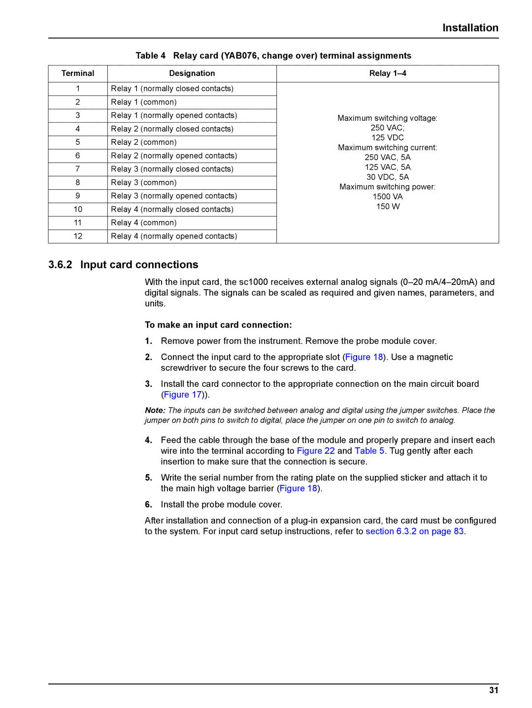
Table 4 Relay card (YAB076, change over) terminal assignments
Terminal |
| Designation | Relay | |
|
|
| ||
1 | Relay 1 (normally closed contacts) |
| ||
|
|
| ||
2 | Relay 1 (common) |
| ||
|
|
| ||
3 | Relay 1 (normally opened contacts) | Maximum switching voltage: | ||
4 | Relay 2 (normally closed contacts) | 250 VAC; | ||
|
|
| 125 VDC | |
5 | Relay 2 (common) | |||
Maximum switching current: | ||||
|
|
| ||
6 | Relay 2 (normally opened contacts) | |||
250 VAC, 5A | ||||
7 | Relay 3 (normally closed contacts) | 125 VAC, 5A | ||
|
|
| 30 VDC, 5A | |
8 | Relay 3 (common) | |||
Maximum switching power: | ||||
|
|
| ||
9 | Relay 3 | (normally opened contacts) | 1500 VA | |
10 | Relay 4 | (normally closed contacts) | 150 W | |
| ||||
|
|
|
| |
11 | Relay 4 | (common) |
| |
|
|
|
| |
12 | Relay 4 | (normally opened contacts) |
| |
|
|
|
| |
3.6.2 Input card connections
With the input card, the sc1000 receives external analog signals
To make an input card connection:
1.Remove power from the instrument. Remove the probe module cover.
2.Connect the input card to the appropriate slot (Figure 18). Use a magnetic screwdriver to secure the four screws to the card.
3.Install the card connector to the appropriate connection on the main circuit board (Figure 17)).
Note: The inputs can be switched between analog and digital using the jumper switches. Place the jumper on both pins to switch to digital, place the jumper on one pin to switch to analog.
4.Feed the cable through the base of the module and properly prepare and insert each wire into the terminal according to Figure 22 and Table 5. Tug gently after each insertion to make sure that the connection is secure.
5.Write the serial number from the rating plate on the supplied sticker and attach it to the main high voltage barrier (Figure 18).
6.Install the probe module cover.
After installation and connection of a
31
