Installation
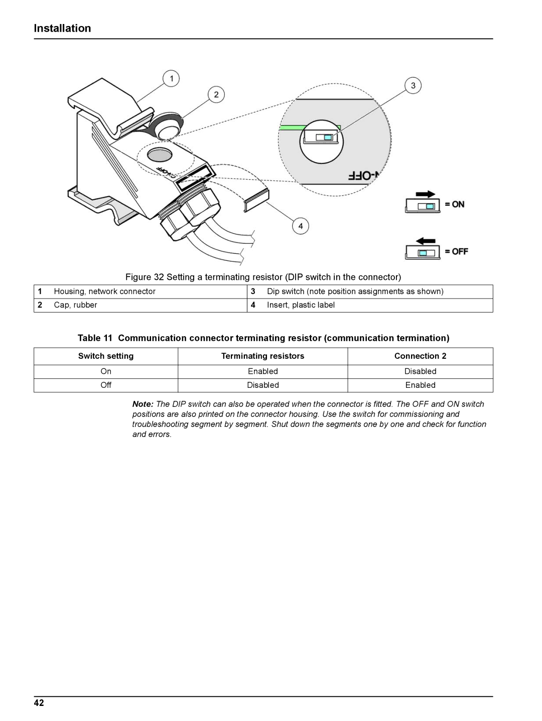
Figure 32 Setting a terminating resistor (DIP switch in the connector)
1 | Housing, network connector | 3 | Dip switch (note position assignments as shown) |
|
|
|
|
2 | Cap, rubber | 4 | Insert, plastic label |
|
|
|
|
Table 11 Communication connector terminating resistor (communication termination)
Switch setting | Terminating resistors | Connection 2 |
|
|
|
On | Enabled | Disabled |
|
|
|
Off | Disabled | Enabled |
|
|
|
Note: The DIP switch can also be operated when the connector is fitted. The OFF and ON switch positions are also printed on the connector housing. Use the switch for commissioning and troubleshooting segment by segment. Shut down the segments one by one and check for function and errors.
42