Installation
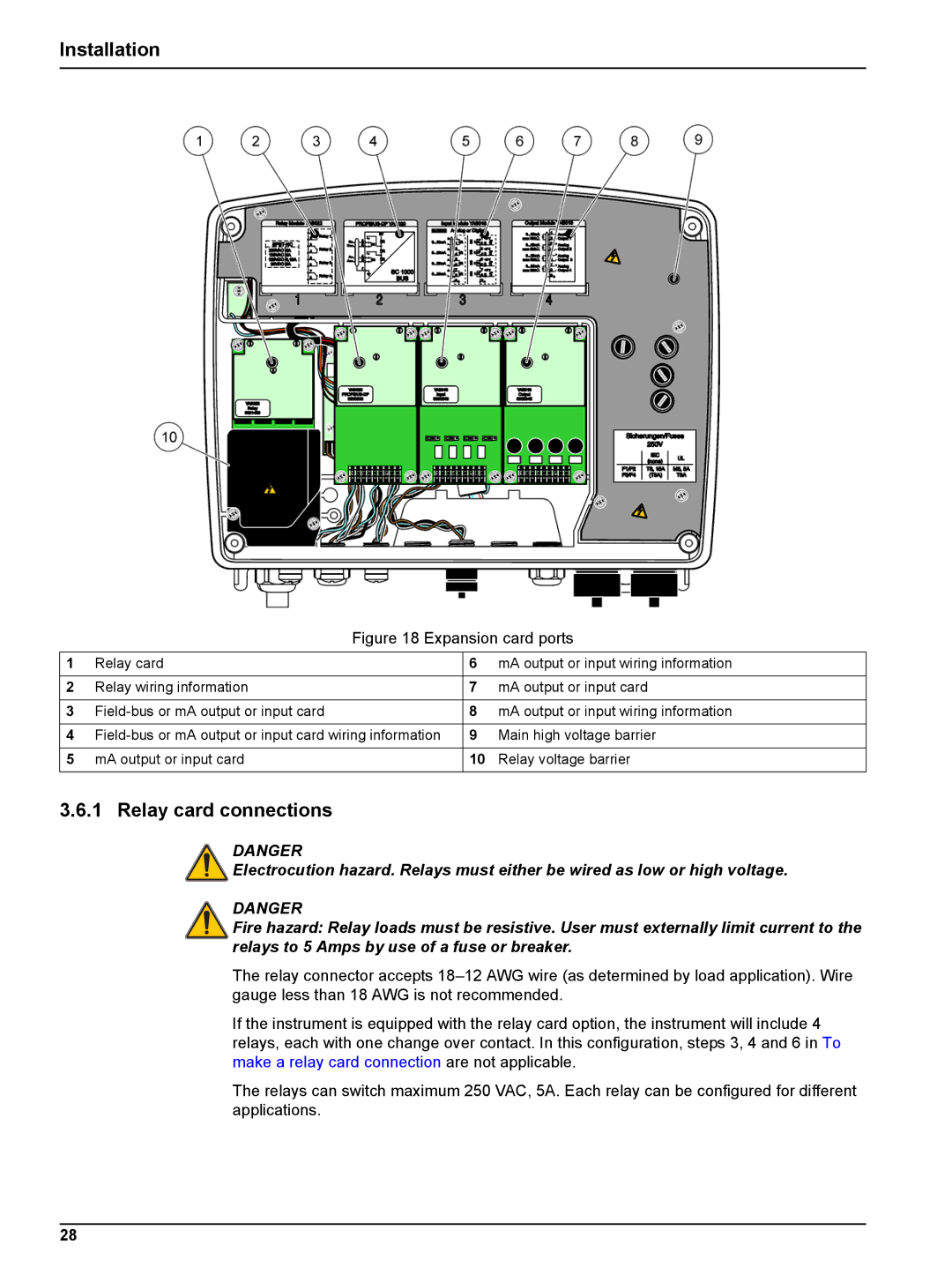
Figure 18 Expansion card ports
1 | Relay card | 6 | mA output or input wiring information |
|
|
|
|
2 | Relay wiring information | 7 | mA output or input card |
|
|
|
|
3 | 8 | mA output or input wiring information | |
|
|
|
|
4 | 9 | Main high voltage barrier | |
|
|
|
|
5 | mA output or input card | 10 | Relay voltage barrier |
|
|
|
|
3.6.1 Relay card connections
DANGER
Electrocution hazard. Relays must either be wired as low or high voltage.
DANGER
Fire hazard: Relay loads must be resistive. User must externally limit current to the relays to 5 Amps by use of a fuse or breaker.
The relay connector accepts
If the instrument is equipped with the relay card option, the instrument will include 4 relays, each with one change over contact. In this configuration, steps 3, 4 and 6 in To make a relay card connection are not applicable.
The relays can switch maximum 250 VAC, 5A. Each relay can be configured for different applications.
28