Advanced Operations
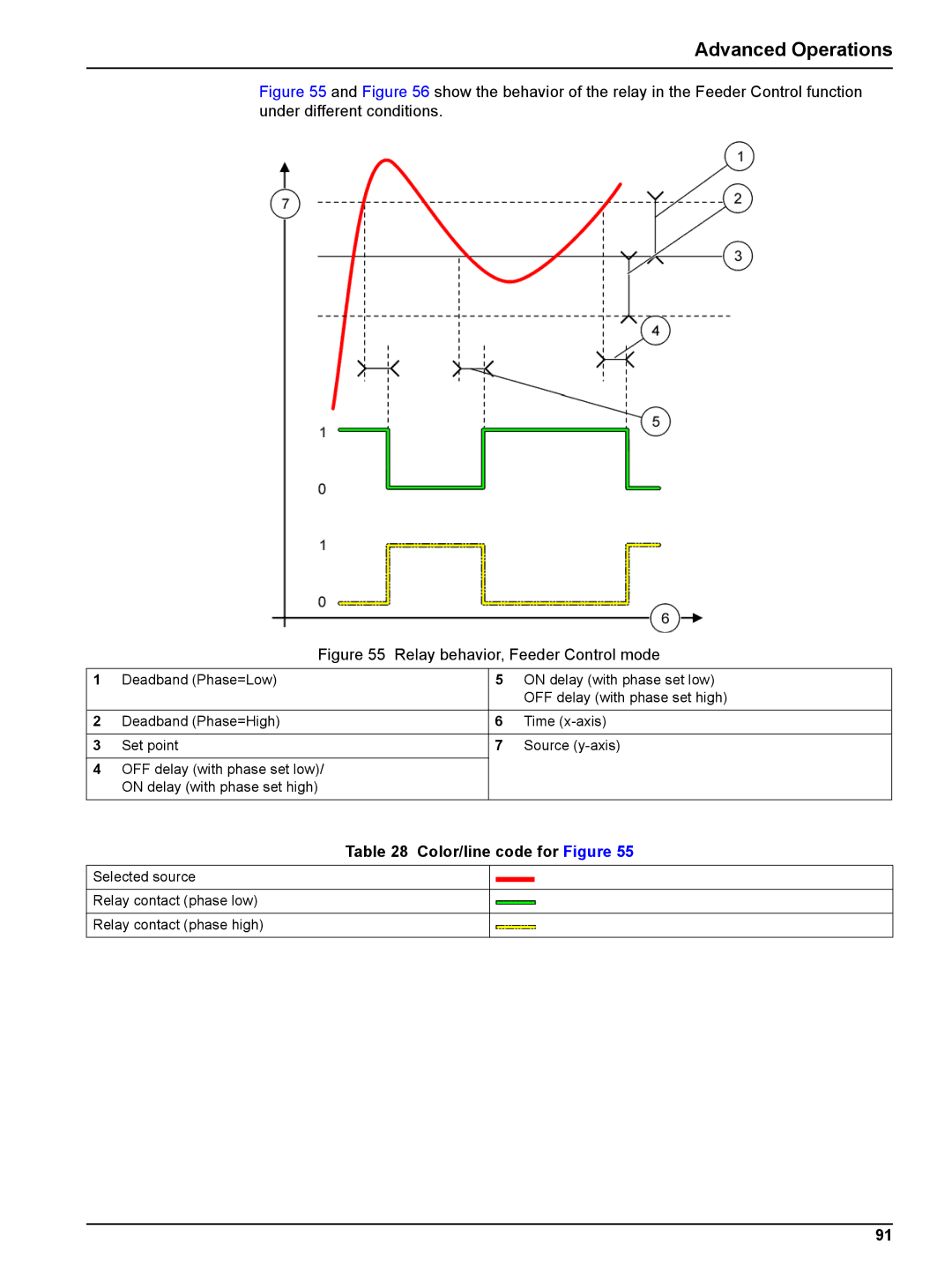
Figure 55 and Figure 56 show the behavior of the relay in the Feeder Control function under different conditions.
| Figure 55 | Relay behavior, Feeder Control mode | ||
1 | Deadband (Phase=Low) |
| 5 | ON delay (with phase set low) |
|
|
|
| OFF delay (with phase set high) |
|
|
|
|
|
2 | Deadband (Phase=High) |
| 6 | Time |
|
|
|
|
|
3 | Set point |
| 7 | Source |
|
|
|
|
|
4 | OFF delay (with phase set low)/ |
|
|
|
| ON delay (with phase set high) |
|
|
|
Table 28 Color/line code for Figure 55
Selected source
Relay contact (phase low)
Relay contact (phase high)
91