Installation
3.4.2 Installation using a power cord
A
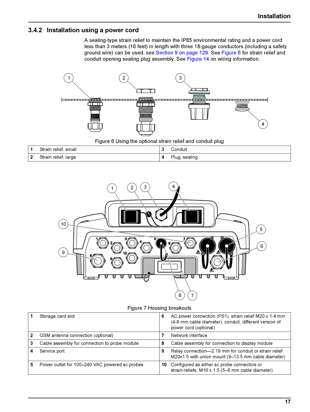
Figure 6 Using the optional strain relief and conduit plug
1 | Strain relief, small | 3 | Conduit |
|
|
|
|
2 | Strain relief, large | 4 | Plug, sealing |
|
|
|
|
Figure 7 Housing breakouts
1 | Storage card slot | 6 | AC power connection (PS1), strain relief M20 x 1.4 mm |
|
|
| |
|
|
| power cord (optional) |
|
|
|
|
2 | GSM antenna connection (optional) | 7 | Network interface |
|
|
|
|
3 | Cable assembly for connection to probe module | 8 | Cable assembly for connection to display module |
|
|
|
|
4 | Service port | 9 | Relay |
|
|
| M20x1.5 with union mount |
|
|
|
|
5 | Power outlet for | 10 | Configured as either sc probe connectors or |
|
|
|
17