Released with BCM
Trademarks
Copyright 2004 Nortel Networks
P0609324
Installation and Maintenance Guide
Safety
North American Regulatory Information
Radio-frequency Interference
Enhanced 911 Configuration
Telecommunication registration
Electromagnetic Compatibility
Network Connection
Hearing Aid Compatibility
Telephone Company Registration
Repairs
Use of a Music Source
Rights of the Telecommunications Company
Canadian Regulations please read carefully
US Regulations please read carefully
Federal Communications Commission FCC Notice
Hearing Aids
Ringer Equivalence Number
Programming Emergency Numbers
Important Safety Instructions
EMI/EMC FCC Part
Use
International Regulatory Information
Additional Safety Information
Safety
Limited Warranty
Exclusions
Warranty Repair Services
After Warranty Service
Contents
Contents
Chapter Telephony hardware
Chapter Selecting the media bay modules for your system
Chapter Setting media bay module DIP switches
Chapter Wiring the modules
Chapter Troubleshooting
Chapter Adding or replacing a cooling fan
Media bay module combinations
Figures
Rear of Gatm module, showing DIP switch locations
Figures
Figures
Tables
Tables
Upgrade notes
Preface
Symbols used in this guide
Preface
Text conventions
Acronyms
DNS
Related publications
System documentation map
Installation documentation
Operations documentation
Call Management documentation
Unified Manager and hardware maintenance documentation
Multi-site Administration Network Configuration Manager
How to get help
Preface P0609324
Chapter Introducing the Business Communications Manager
Business Communications Manager system components
Hardware components
Computer components
Introducing the Business Communications Manager
Basic BCM1000 base unit specifications
BCM1000 interior components for standard system pre-2.5
Power supply Fan
Introducing the Business Communications Manager
Telephony components
Introducing the Business Communications Manager
Media Services Card
Data networking components
MSC IP call processing hardware
Connection ports
BCM1000 external points of connection
BCM1000 LEDs
BCM1000 operational LEDs
Telephony features and options
System options
CallPilot Reference Guide
Data features
LAN CTE Configuration Guide
Refer to , Installing the BCM1000, on
Business Communications Manager expansion unit
DS256 connector on a BCM1000 and a BCM1000e
Installation process overview
Installation and initialization overview
Installation overview
Chapter Telephony hardware
LED state Power Status
Media bay module common features
Module Power and Status LED states
LEDs
Flashing
Power connections
LED state Power Status Green LED
Off
DIP switches
DIP switch positions on the modules
Trunk media bay modules
Trunk media bay modules
Module type What it does Special notes
DTM LED functions
Digital Trunk media bay module
Front view
LED label Function
Global Analog Trunk Module Gatm
GATM4/GATM8 module faceplate
Caller ID Trunk media bay module
North American systems only
Basic Rate Interface media bay module
CTM and CTM8 LEDs and jacks
Station modules
Station media bay modules
Module type What it does Availability
Digital Station media bay module
Faceplates of DSM 16/DSM 16+ and DSM 32/DSM32+
4X16 media bay module
Analog Station media bay module
Global Analog Station media bay module ASM8+
ASM 8 front view
Region-specific application
Specialized media bay modules
Dect media bay module
Specialized modules
Dect faceplate with eight RJ45 connectors
Fiber Expansion media bay module
Telephones and adapters
Not shown
Nortel IP telephones
Auxiliary equipment
Companion system components
Portable systems
Dect system components
BST 7406 system components
NetVision system components
Chapter Auxiliary requirements
Computer specifications
Security changes
Browser requirements
Auxiliary requirements
Preloading Java class files on your workstation
Using an Http Proxy server
Optimizing Unified Manager speed
Auxiliary requirements P0609324
Chapter Selecting the media bay modules for your system
Process for determining modules
Selecting the media bay modules for your system
Selecting the trunk media bay modules
Determining trunk module requirements
An example
Selecting the station media bay modules
Station media bay modules required
Understanding DS30 bus blocks
Upgrading from an existing Norstar system
Determining system capacity
Changing the DS30 split
Explaining Double Density
DS30 bus model
Setting Offsets
Determining module DS30 bus requirements
Matching modules to DS30 bus capacity
Channel split 2/6 default
Type of module Number required DS30 bus/offsets required
Selecting the media bay modules for your system P0609324
Preparation checklist
Chapter Installing the BCM1000
Environment checklist
Electrical requirements
Internal wiring requirements
Installing the BCM1000
Digital loop
Optional equipment
System equipment and supplies
Basic hardware
Analog loop
Companion equipment
Equipment for Installing the BCM1000
Other cordless systems
Installing the BCM1000 in a rack
Attaching the rack mounting brackets
Installing the BCM1000 into the rack
Fasten the BCM1000 to the equipment rack P0609324
Installing the BCM1000 on the wall
Attaching the mounting brackets to the BCM1000
Mount the BCM1000 on the wall
Installing the BCM1000 on a flat surface
Replacing your BCM1000 hardware
Installing the BCM1000e into a rack
Chapter Installing the BCM1000e expansion unit
Attaching the mounting brackets
Installing the BCM1000e expansion unit
Attaching the BCM1000e to the rack
Installing the BCM1000e on the wall
Installing the BCM1000e on a flat surface
Connecting the BCM1000e to the BCM1000
BCM1000 DS258 connector
Installing the BCM1000e expansion unit P0609324
Chapter Setting media bay module DIP switches
Rules for assigning DS30 bus blocks and offsets
Setting media bay module DIP switches
Choosing the assigned order for modules
DS30 split
Double-density example
DSM 32 4x16 ASM DTM
Determining module DIP switch settings
Offset DS30
DIP switch settings
Media bay module positioning
Media bay module
DIP switch settings DS30
Positioning
Setting the DIP switches on the modules
Switches on the media bay module
DTM switch settings
Line and extension numbers for specific modules
DTM switch settings E1 and UK PRI
BRI switch settings
Brim S/T switch settings
CTM/GATM switch settings
Gatm switch settings
Country select P0609324
Select Enter these switch settings To assign DS30
CTM/GATM DIP switch settings
CTM/GATM4 and CTM8/GATM8 DS30 and offset switch settings
To assign these lines
Global Analog Trunk Module DIP switch settings
Country select DIP switch settings
61-64 69-72 77-80 85-88
To assign This Custom DN
4X16 switch settings
4X16 switch settings Select
Range
99-102 301-316
107-110 Upgrade
Bus # DNs 91-94 DS30
381-396 115-118 New
Select Enter these switch To assign these DNs Bus#
ASM 8/ASM8+ switch settings
ASM8 settings for upgraded 2.5 systems and new 3.0 systems
Settings System New 3.0 system Upgraded to
ASM8+ country switch settings
To assign these DNs to DSM16 or DSM 16+
DSM switch settings
ASM8+ country select dip switch settings
DNs to DSM 32 or DSM 32+
DS30 05 285-300 285-316 565-5803
DS30 03 253-268 253-284
DS30 04 269-284 269-300
DS30 06
To DSM 32+ Custom DN Connectors Range
To assign these DNs to DSM 16+ =DSM1, B=DSM2
To DSM 16+
DSM 32+ connectors
Select DS30 Bus #
=top, B = bottom
Select Set the switches Use these
Dect switch settings
Dect module settings
DNs on DS30 Offset Custom DN range Newer
FEM switch settings
FEM switch settings
Chapter Installing media bay modules
Process map Installing a media bay module
Installing media bay modules
Shutting down the system
Installing a media bay module
Removing the front bezel
Module daughter board wiring
Reconnecting the equipment
Replacing media bay modules
Process map Replacing a media bay module Module Failure
Installation/replacement troubleshooting
Installing media bay modules P0609324
Chapter Starting the system
Checking power and wiring
Starting the system
Checking system power and status
LEDs confirm that BCM1000 is active
BCM1000 LED states
Connecting the data networking hardware
Connecting the cards
Connecting wiring to the LAN card
Connect wiring to the WAN card
DB25 adapter cable
Connect wiring to the modem card
DB26 on WAN card Signal DB25 cable
North American Systems only
RS-422/EIA 530 adapter cable
DB26 on RS-422/EIA WAN card Signal Cable
DB26 on WAN card Signal Cable
35 Adapter Cable
Replacing the cards
DB26 on DB15 WAN card Signal Cable
DB15 X.21 adapter cable
Default IP settings
Setting initial system configurations
Required data parameters
Pin Signal
Connecting when there is an IP address conflict
Using a null modem serial cable
Serial port pinout Serial pinout
Finding the configuration menus
Main Menu
Using an Ethernet crossover cable
Ethernet crossover cable
Regenerating keys after system replacement
Entering the software keycodes
Starting the system P0609324
Chapter Wiring the modules
Wiring the modules
Module wiring warnings
Trunk and station modules
To network To plug
Connecting media bay modules to Service Providers
Pin #/connection
Gatm cable wiring diagram
Connector pinout Line Pin Wire color Gatm module
BRI RJ45 wiring array
Pin #/connection System side
Wiring media bay modules to internal connections
Use and on
DSM wiring chart
Sets Pin Wire color Port 1st 2nd
ASM wiring chart
Pin Wire color Port Set
FEM wiring
Connecting the fiber cables
Extension comparison chart
System telephones
Chapter Installing telephones and peripherals
Analog terminal adapter
Central Answering Position CAP/eCAP
Installing telephones and peripherals
Telephone port and DN cross-reference
Pins Port
Bus DNs
Bus Pins Port DNs
Second-level DNs DS 30 bus set to Full Double Density
Installing an emergency telephone
Installing IP telephones
Companion portable system legacy hardware
Installing radio-based portable systems
Dect systems region specific
T7406 Cordless Telephone Installation Guide provides
T7406 cordless systems
Installing telephones and peripherals P0609324
Chapter Installing Analog Terminal Adapters
Understanding pre-installation requirements
Installing Analog Terminal Adapters
Analog transmission parameters North American systems, only
Connecting an analog telephone
Connecting a data device
Connecting the ATA
Telephone jack
Mounting the ATA
Testing insertion loss measurement
Insertion loss from the CO to the analog telephone
Configuring the ATA
For analog device to CO measurement
Installing Analog Terminal Adapters P0609324
Auxiliary ringer programming
Chapter Installing optional telephony equipment
Auxiliary ringer
Customer supplied
Installing optional telephony equipment
Connecting the paging system
External paging system
Music on hold specifications
External music source
Connecting the external music source
External music source programming
Chapter Troubleshooting
Using the System Status Monitor to monitor LEDs
Troubleshooting
Under Diagnostics, click on System Status Monitor
Emergency telephone does not function
LED Display screen settings
Attribute Values Description
Checking the wiring
ATA 2 does not function
Checking for dial tone at the ATA
Checking for trunk line dial tone to the ATA
Chapter Preparing hardware for maintenance or upgrades
Special tools
Preparing hardware for maintenance or upgrades
Shutting down the system software
Shutting down the system hardware
Removing the top cover from the unit
Removing the front bezel
Restarting the system
Restoring the system to operation
Software restart
Preparing hardware for maintenance or upgrades P0609324
Remove the damaged hard disk from the brackets
Chapter Replacing the hard disk
Single Disk Upgrading to Mirrored Disk System Mirrored disk
Test all functions
Removing the hard disk
Replacing the hard disk
Hard disk and screw locations 2.5 version hardware
Remove the brackets from the hard disk
Installing a new hard disk
Connect the brackets to the hard disk single-disk system
Mirrored hard disks
Initializing the hard disk single-disk system, BCM 2.5/2.5.1
Platform Initialization Menu screen BCM 2.5/2.5.1 systems
Profile screen
Initializing the hard disk single-disk system, BCM
Platform Initialization Menu screen
MSC Initialization Menu screen
Replacing the hard disk
Main Menu screen
BCM1000
Select 1 Initialize Universal Profile and press Enter
System configuration start
Quick start
Installing the mirrored disk controller
Base unit with RAID board, plus redundant power and fans
Installing the RAID board
Clip the RAID board onto the media bay module housing
Connecting the RAID board
RAID board LEDs on face of base unit
Connecting RAID board ribbon cables
Shows the location of these connectors on the RAID board
Routing power for mirrored systems
Power routing for 2.5 hardware
Power routing for 2.0 hardware
RAID board LED states
RAID board LEDs
LED state Primary and Mirror LEDs Status LEDs
HDD Mirror Settings
Controlling and monitoring mirroring operations
Chapter Adding or replacing a cooling fan
Or Temp. LED Indicate Problem
Set up unit for Connect fan
Operation
Adding or replacing a cooling fan
Troubleshooting fan operation
Removing a fan from the BCM1000
LED Label Description Green LED On Red LED On Only
Remove the fan cable from motherboard pre-2.5 chassis
Removing the fan BCM1000 version 2.5 single-fan model
Installing piggy-backed fans
Replacing the cooling fan
Removing a fan from the BCM1000e
Connect the redundant fan cable to the adapter
FAN
Replacing a fan into the BCM1000e
Chapter Replacing a power supply
Replacing a standard power supply
Removing the standard power supply
Replacing a power supply
Installing a standard power supply
Version 2.5 hardware
Power supply LED
Upgrading to a redundant power supply
At least one power supply Requires attention
Setting up the base unit
System Status Monitor internal connectors
Installing the redundant power supply
Remove the knockout
Attach the redundant power supply housing
Power supply bracket screw
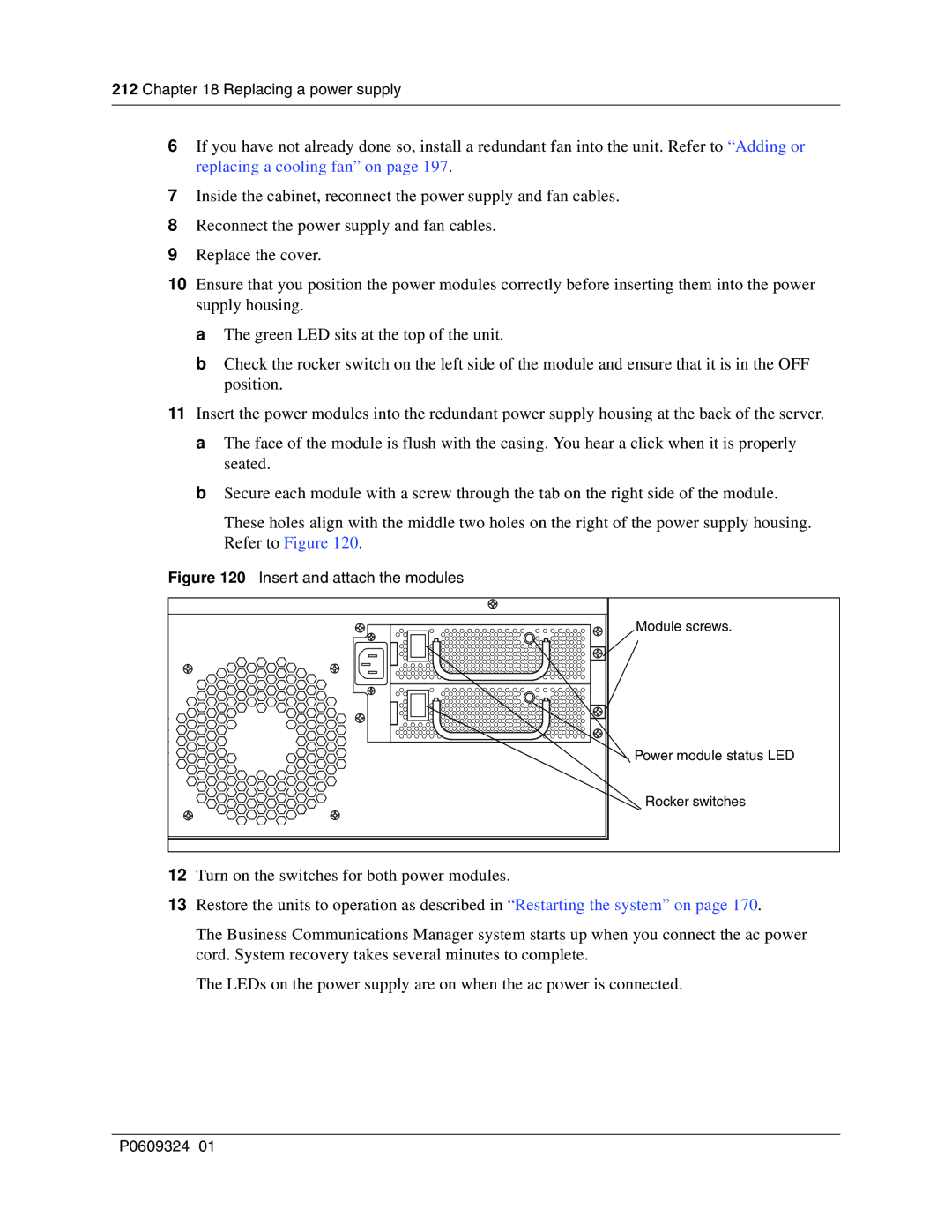
Insert and attach the modules
Replacing a redundant power supply module
Removing the power module
Replacing a power supply in an BCM1000e
122 BCM1000e, standard power supply interior connections
BCM1000e, redundant power supply interior connections
Replacing a power supply P0609324
Chapter Replacing data cards and processing hardware
Replacing data cards
Replacing data cards and processing hardware
Removing a data card
BCM1000 PCI LED states
Installing the card
Install the LAN card Installation and Maintenance Guide
Process Map PEC replacement
Replacing PECs
Removing PECs
Installing a PEC
Process Map Memory replacement
Replacing memory
Replacing memory Dimm chips
Removing and replacing the DIMMs
Replacing the clock/calendar battery
Process Map Battery replacement overview
Removing the clock/calendar battery
Removing the clock/calendar battery
Installing the new battery
Replacing data cards and processing hardware P0609324
Determining the status of a telephone
Chapter Moving and replacing telephones
Moving and replacing telephones
Moving telephones
Replacing telephones with different models
Status of the replaced telephone
Moving and replacing telephones P0609324
Core software, defined by region and carrier profile
Appendix a System region attributes
Core software and regions
Brazil Caribbean Denmark Australia Hong Kong France
Languages
Companding law
Caller ID displays
Companding law by region
Companding Law Mu-law
Isdn services, by Protocol
Isdn line services
Isdn line services
Protocol Available Isdn services
Media bay module availability by region
Mobility services by region
Mobility services, by region
Module availability, by profile
PRI line protocol supported, by region
PRI line protocol support, by region
Region BRI T side BRI S side
Country
Trunk availability by region
Trunk availability, by region
Specific
DASS2 Dpnss Mcdn
BRI and PRI line types DTM and BRI modules
BRI and PRI line types
Digital trunk types Description
Time/date formats based on language
Defining time zones by country and language
Language/Country Time/Date format
System defaults
Region defaults
Appendix a System region attributes Region defaults
Utam
Appendix a System region attributes P0609324
CTMs/GATMs combined with 4X16 modules
Appendix B Media bay module combinations
Combining CTMs/GATMs and 4X16s
CTMs/GATM4s
Appendix B Media bay module combinations
Fully-loaded setup
DSM 32 settings
DSM combined with 2 DTMs and 2 ASMs
Fully loaded system using modules set to double density
To DD ASM8+s DTMs Offset Offset 0, 1, 2 DSM settings Ports
Three BRI modules, two DSM 32s and 1 Dect module
Switch setting DS30
Dect combinations
Each heavily-outlined and shaded square
Set to PRI Set to DD Bus #
Double density system with Dect module
DTM DSM 32+ DSM16+ DS30
Offset 0 Ports
System setup
Changing configurations
DS30 bus
Set DNs and port numbers
Cross referencing ports and DNs
P0609324
Glossary
Glossary
Call log
Camp timeout
Channel service unit CSU
Camp-on
Digital Private Network Signaling System Dpnss
Companion Wireless
Delayed Ring Transfer DRT to prime
Conference
Do Not Disturb
Disconnect supervision
Disk mirroring
Domain name
External call
Feature code
Event message
External line
Handsfree HF Answerback
Integrated Services Digital Network Isdn
Handsfree
Held Line Reminder
IP address server
Internet Protocol IP
IP address
Kbyte
Mailbox
Link
Local Area Network LAN
Meridian 1 Isdn Primary Rate Interface
Network device
Network Basic Input/Output System NetBIOS
Network
Network DN
Personal Speed Dial
Parallel port
Peripheral Component Interconnect PCI Slot
Pin-1
Random Access Memory RAM
Quality of Service QoS
Reference point signalling Qsig
Remote access
Read Only Memory ROM
Station Auxiliary Power Supply Saps
Restriction filter
Router
Telephony Application Program Interface Tapi
System speed dial code
Target lines
Transfer
Voice over IP VoIP
Weighted Fair Queuing WFQ
Voice Message Center
Wide Area Network WAN
Glossary P0609324
Index
Numerics
Index
BRI
Clid
CTM
Installation and Maintenance Guide
EMI/EMC
RAID
LAN CTE
Installation and Maintenance Guide
MSC
PCI
RPI
Saps
Tapi LAN CTE
WAN