Installation Information
11.The Remote EPO feature opens all contactors in the UPS cabinet and isolates power from your critical load. Local electrical codes may also require tripping upstream protective devices to the UPS. This switch must be a dedicated
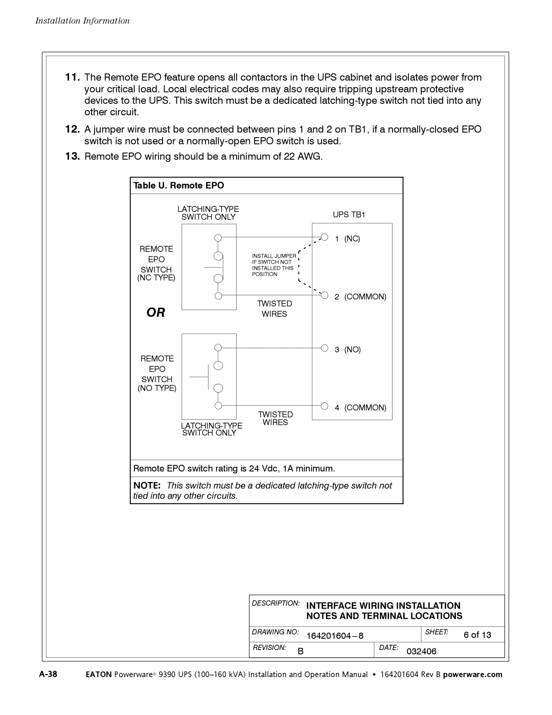
12.A jumper wire must be connected between pins 1 and 2 on TB1, if a
13.Remote EPO wiring should be a minimum of 22 AWG.
Table U. Remote EPO
| UPS TB1 | |
SWITCH ONLY |
| |
|
| 1 (NC) |
REMOTE | INSTALL JUMPER |
|
EPO |
| |
IF SWITCH NOT |
| |
SWITCH | INSTALLED THIS |
|
(NC TYPE) | POSITION |
|
|
| |
| TWISTED | 2 (COMMON) |
OR |
| |
WIRES |
| |
REMOTE |
| 3 (NO) |
|
|
EPO
SWITCH
(NO TYPE)
TWISTED
SWITCH ONLY
4 (COMMON)
Remote EPO switch rating is 24 Vdc, 1A minimum.
NOTE: This switch must be a dedicated
DESCRIPTION: INTERFACE WIRING INSTALLATION
NOTES AND TERMINAL LOCATIONS
| DRAWING NO: |
| SHEET: | 6 of 13 |
| REVISION: B | DATE: 032406 |
| |