Using the Control Panel
9.5Reading the Status Indicators
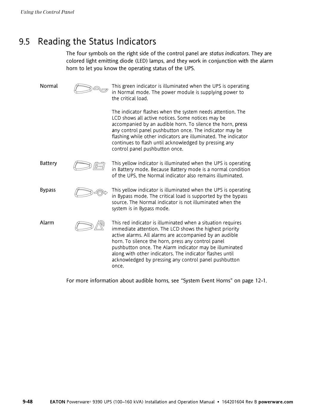
The four symbols on the right side of the control panel are status indicators. They are colored light emitting diode (LED) lamps, and they work in conjunction with the alarm horn to let you know the operating status of the UPS.
Normal | This green indicator is illuminated when the UPS is operating |
| in Normal mode. The power module is supplying power to |
| the critical load. |
| The indicator flashes when the system needs attention. The |
| LCD shows all active notices. Some notices may be |
| accompanied by an audible horn. To silence the horn, press |
| any control panel pushbutton once. The indicator may be |
| flashing while other indicators are illuminated. The indicator |
| continues to flash until acknowledged by pressing any |
| control panel pushbutton once. |
Battery | This yellow indicator is illuminated when the UPS is operating |
| in Battery mode. Because Battery mode is a normal condition |
| of the UPS, the Normal indicator also remains illuminated. |
Bypass | This yellow indicator is illuminated when the UPS is operating |
| in Bypass mode. The critical load is supported by the bypass |
| source. The Normal indicator is not illuminated when the |
| system is in Bypass mode. |
Alarm | This red indicator is illuminated when a situation requires |
| immediate attention. The LCD shows the highest priority |
| active alarms. All alarms are accompanied by an audible |
| horn. To silence the horn, press any control panel |
| pushbutton once. The Alarm indicator may be illuminated |
| along with other indicators. The indicator flashes until |
| acknowledged by pressing any control panel pushbutton |
| once. |
| For more information about audible horns, see “System Event Horns” on page |