Installation Information
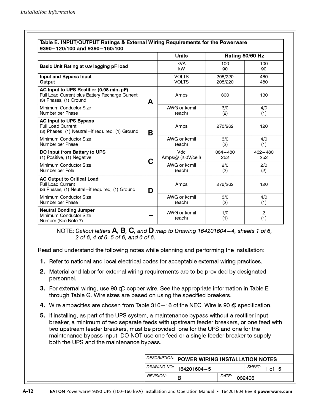
Table E. INPUT/OUTPUT Ratings & External Wiring Requirements for the Powerware
|
| Units | |
|
|
| |
Basic Unit Rating at 0.9 lagging pF load |
| kVA | |
| kW | ||
|
| ||
|
|
| |
Input and Bypass Input |
| VOLTS | |
Output |
| VOLTS | |
|
|
| |
AC Input to UPS Rectifier (0.98 min. pF) |
|
| |
Full Load Current plus Battery Recharge Current | A | Amps | |
(3) Phases, (1) Ground |
| ||
|
| ||
Minimum Conductor Size |
|
| |
| AWG or kcmil | ||
Number per Phase |
| (each) | |
|
|
| |
AC Input to UPS Bypass |
|
| |
Full Load Current | B | Amps | |
(3) Phases, (1) |
| ||
|
| ||
Minimum Conductor Size |
|
| |
| AWG or kcmil | ||
Number per Phase |
| (each) | |
|
|
| |
DC Input from Battery to UPS |
| Vdc | |
(1) Positive, (1) Negative | C | Amps@ (2.0V/cell) | |
Minimum Conductor Size |
| AWG or kcmil | |
Number per Pole |
| (each) | |
|
|
| |
AC Output to Critical Load |
|
| |
Full Load Current | D | Amps | |
(3) Phases, (1) |
| ||
Minimum Conductor Size |
| AWG or kcmil | |
Number per Phase |
| (each) | |
|
|
| |
Neutral Bonding Jumper | AWG or kcmil | ||
Minimum Conductor Size | |||
(each) | |||
Number (See Note 7) |
|
|
Rating 50/60 Hz
100100
9090
208/220 | 480 |
208/220 | 480 |
|
|
300 | 130 |
3/0 |
|
4/0 |
(2)(1)
278/262 | 120 |
3/0 |
|
4/0 |
(2)(1)
252 | 252 |
2/0 |
|
2/0 |
(2)(2)
278/262 | 120 |
|
|
3/0 | 4/0 |
(2)(1)
1/0 | 2 |
(1)(1)
NOTE: Callout letters A, B, C, and D map to Drawing 164201604
Read and understand the following notes while planning and performing the installation:
1.Refer to national and local electrical codes for acceptable external wiring practices.
2.Material and labor for external wiring requirements are to be provided by designated personnel.
3.For external wiring, use 90° C copper wire. See the appropriate information in Table E through Table G. Wire sizes are based on using the specified breakers.
4.Wire ampacities are chosen from Table
5.If installing, as part of the UPS system, a maintenance bypass without a rectifier input breaker, a minimum of two separate feeds with upstream feeder breakers, or one feed with two upstream feeder breakers, must be provided: one for the UPS and one for the maintenance bypass input. DO NOT use one feed or a
| DESCRIPTION: | POWER WIRING INSTALLATION NOTES | ||
|
|
|
|
|
| DRAWING NO: |
| SHEET: 1 of 15 | |
| REVISION: | B | DATE: 032406 | |