Installation Information
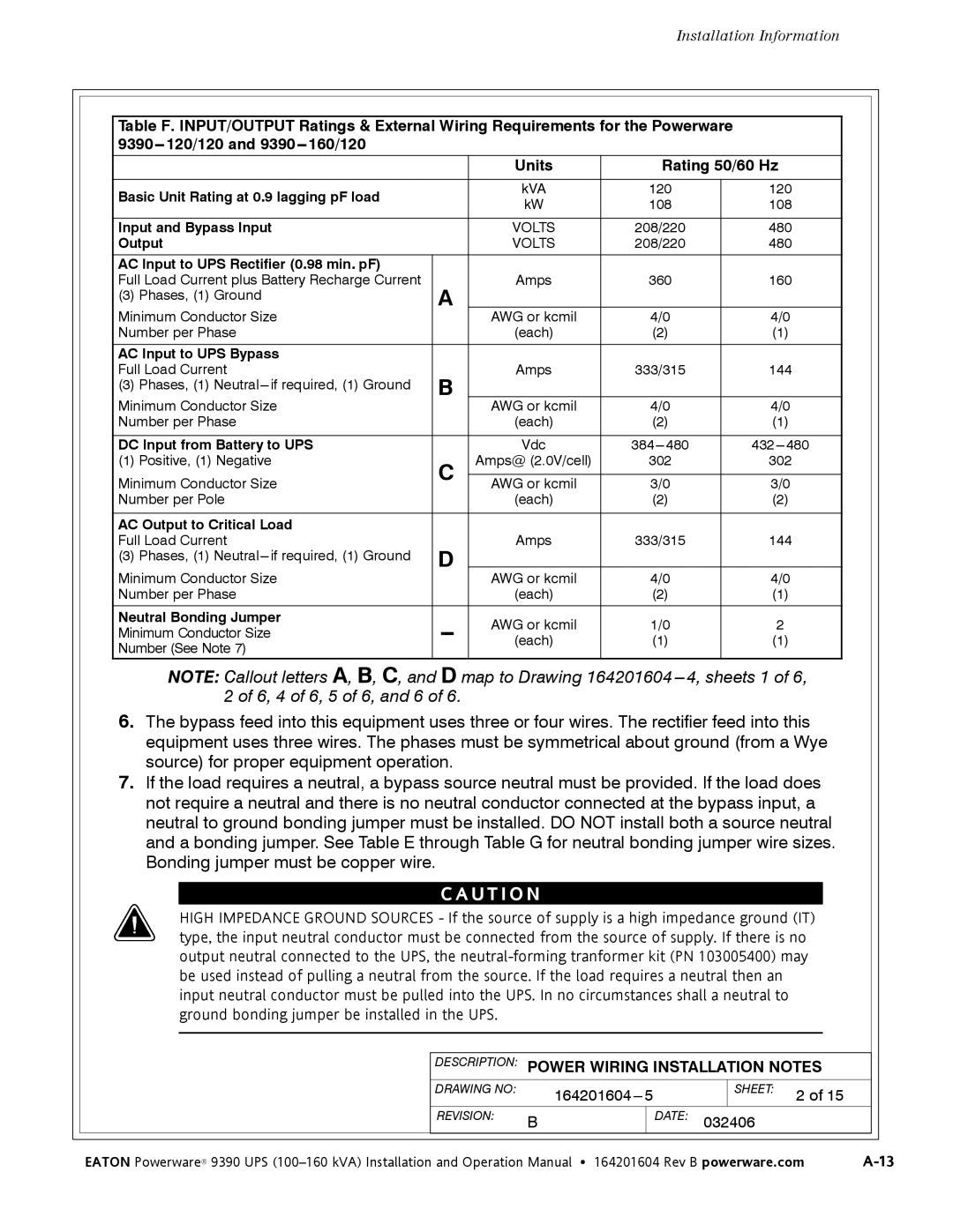
Table F. INPUT/OUTPUT Ratings & External Wiring Requirements for the Powerware
|
| Units | |
|
|
| |
Basic Unit Rating at 0.9 lagging pF load |
| kVA | |
| kW | ||
|
| ||
|
|
| |
Input and Bypass Input |
| VOLTS | |
Output |
| VOLTS | |
AC Input to UPS Rectifier (0.98 min. pF) |
|
| |
Full Load Current plus Battery Recharge Current | A | Amps | |
(3) Phases, (1) Ground |
| ||
Minimum Conductor Size |
| AWG or kcmil | |
Number per Phase |
| (each) | |
|
|
| |
AC Input to UPS Bypass |
|
| |
Full Load Current | B | Amps | |
(3) Phases, (1) |
| ||
Minimum Conductor Size |
| AWG or kcmil | |
Number per Phase |
| (each) | |
|
|
| |
DC Input from Battery to UPS |
| Vdc | |
(1) Positive, (1) Negative | C | Amps@ (2.0V/cell) | |
Minimum Conductor Size |
| AWG or kcmil | |
Number per Pole |
| (each) | |
|
|
| |
AC Output to Critical Load |
|
| |
Full Load Current | D | Amps | |
(3) Phases, (1) |
| ||
Minimum Conductor Size |
| AWG or kcmil | |
Number per Phase |
| (each) | |
|
|
| |
Neutral Bonding Jumper | AWG or kcmil | ||
Minimum Conductor Size | |||
(each) | |||
Number (See Note 7) |
|
|
Rating 50/60 Hz
120120
108108
208/220 | 480 |
208/220 | 480 |
|
|
360 | 160 |
4/0 |
|
4/0 |
(2)(1)
333/315 | 144 |
4/0 |
|
4/0 |
(2)(1)
302 | 302 |
3/0 |
|
3/0 |
(2)(2)
333/315 | 144 |
|
|
4/0 | 4/0 |
(2)(1)
1/0 | 2 |
(1)(1)
NOTE: Callout letters A, B, C, and D map to Drawing 164201604
6.The bypass feed into this equipment uses three or four wires. The rectifier feed into this equipment uses three wires. The phases must be symmetrical about ground (from a Wye source) for proper equipment operation.
7.If the load requires a neutral, a bypass source neutral must be provided. If the load does not require a neutral and there is no neutral conductor connected at the bypass input, a neutral to ground bonding jumper must be installed. DO NOT install both a source neutral and a bonding jumper. See Table E through Table G for neutral bonding jumper wire sizes. Bonding jumper must be copper wire.
C A U T I O N
HIGH IMPEDANCE GROUND SOURCES - If the source of supply is a high impedance ground (IT) type, the input neutral conductor must be connected from the source of supply. If there is no output neutral connected to the UPS, the
|
| DESCRIPTION: | POWER WIRING INSTALLATION NOTES |
|
|
| ||||
|
|
|
|
|
|
|
|
|
|
|
|
| DRAWING NO: |
| SHEET: | 2 of 15 |
|
|
| ||
|
|
|
|
|
|
|
| |||
|
| REVISION: | B |
| DATE: 032406 |
|
|
|
| |
|
|
|
|
|
|
|
|
|
|
|
| EATON Powerware® 9390 UPS | |||||||||