Understanding UPS Operation
7.3.3 Bypass Mode – Parallel
In Bypass mode, the output of the system is provided with
The parallel system automatically switches to Bypass mode if it detects a UPM overload, UPMs unavailable, load fault, or internal failure.
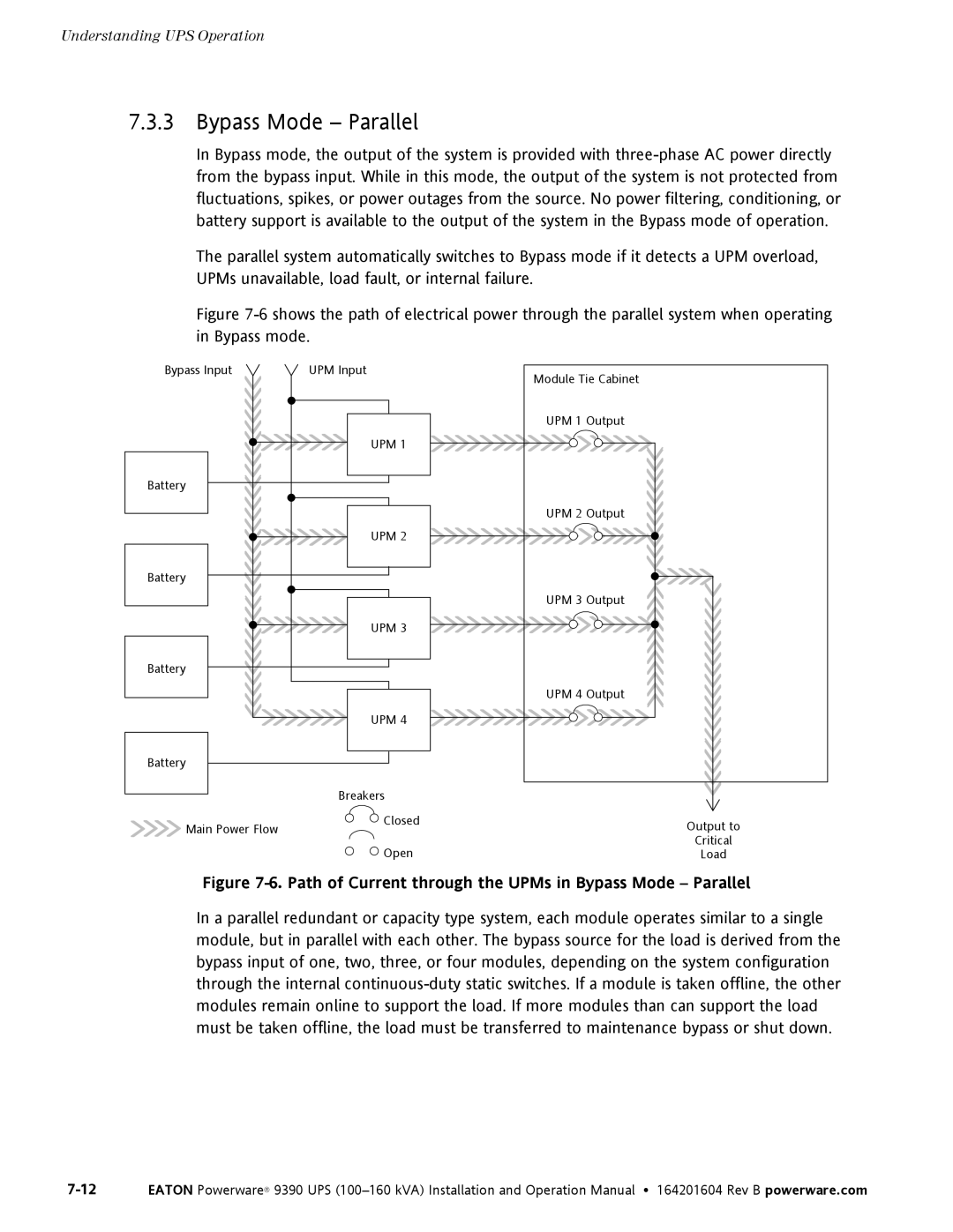
Figure 7-6 shows the path of electrical power through the parallel system when operating in Bypass mode.
Bypass Input | UPM Input |
| UPM 1 |
Battery |
|
| UPM 2 |
Battery |
|
| UPM 3 |
Battery |
|
| UPM 4 |
Battery |
|
Module Tie Cabinet
UPM 1 Output
UPM 2 Output |
UPM 3 Output |
UPM 4 Output |
| Breakers |
|
Main Power Flow | Closed | Output to |
| ||
| Open | Critical |
| Load |
Figure 7-6. Path of Current through the UPMs in Bypass Mode – Parallel
In a parallel redundant or capacity type system, each module operates similar to a single module, but in parallel with each other. The bypass source for the load is derived from the bypass input of one, two, three, or four modules, depending on the system configuration through the internal